Lighting artificial tooth placing rack

A technology for placing racks and dentures, which is applied in medical science, dentistry, dental prosthesis, etc., to achieve the effect of simple structure, convenient use and beautiful appearance

Inactive Publication Date: 2016-03-30
QINGDAO HUAXINHUA DENTAL
View PDF0 Cites 0 Cited by
  • Summary
  • Abstract
  • Description
  • Claims
  • Application Information

AI Technical Summary

Problems solved by technology

At present, neither the denture factory nor the dental clinic has a good base for placing dentures.

Method used


Image

  • Lighting artificial tooth placing rack

Examples


Embodiment Construction

[0009] The present invention will be further described below in conjunction with the drawings:

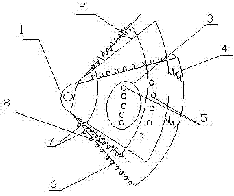
[0010] As shown in the figure, an illuminable denture placement rack is mainly composed of connecting body 1, upper hinge of base 2, telescopic airbag 3, spring 4, suction hole 5, lower hinge of base 6, luminous body 7, dust prevention device 8 composition, characterized in that: the upper hinge 2 of the base is connected with the connecting body 1, the lower hinge 6 of the base is connected with the connecting body 1, and the telescopic airbag 3 is connected with the upper hinge 2 of the base Connected to the bottom hinge 6 of the base, the spring 4 is connected to the upper hinge 2 of the base and the bottom hinge 6 of the base, the suction hole 5 is on the hinge 2 on the base, the The luminous body 7 is connected with the bottom hinge 6 of the base, and the dust prevention device 8 is connected with the bottom hinge 6 of the base.

[0011] The function of the connecting body 1 is to...


PUM


Abstract

The invention relates to a lighting artificial tooth placing rack mainly composed of a connecting body, a base upper hinge, a telescopic gas bag, springs, gas suction holes, a base lower hinge, luminous bodies and a dust-proof device. The lighting artificial tooth placing rack is characterized in that the lighting artificial tooth placing rack has the advantages of simple structure, convenient use and beautiful appearance, and is a good base for placing artificial teeth.

Description

Technical field [0001] The invention relates to a dental tool, in particular to a illuminating denture placement frame. Background technique [0002] Dentures are dentures inserted to restore the functions of chewing, beauty, pronunciation, etc. after tooth loss or extraction. Overdenture refers to a complete denture or removable partial denture in which the base of the denture covers and supports the treated tooth root and crown. There are abutments under the base of the denture, so the absorption of alveolar bone is reduced, and the retention, stability and support of the denture can be enhanced. If a complete denture is used, a flesh-colored acrylic base needs to be attached to your gums. The base of the upper denture should cover the upper palate, and the base of the lower denture is horseshoe-shaped due to the tongue. At present, neither denture manufacturers nor dental clinics have a good base for placing dentures. Summary of the invention [0003] In order to solve the ...

Claims


Application Information

Patent Timeline
IPC IPC(8): A61C13/12
CPCA61C13/12
Inventor 都正杰郑伟陶小龙
Owner QINGDAO HUAXINHUA DENTAL
Why Eureka
Try Eureka