Novel knockout head of casting mold
A technology for casting molds and blowing heads, which is applied to casting molding equipment, parts of molding machines, molding machines, etc. It can solve the problems of affecting the normal use of molds, manual cleaning omissions, and increased production costs, so as to improve blowing efficiency and effect, avoiding a large amount of lifting, and improving efficiency
- Summary
- Abstract
- Description
- Claims
- Application Information
AI Technical Summary
Problems solved by technology
Method used
Image

Examples
Embodiment 1
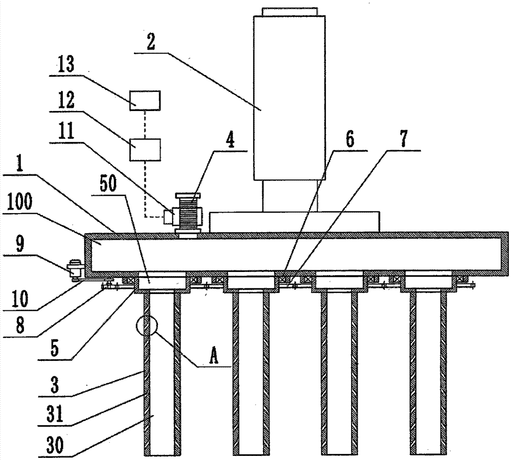
[0017] Such as figure 1 As shown, the shakeout head of the new casting mold of this embodiment includes a fixed seat 1, a lifting cylinder 2 is installed on the upper surface of the fixed seat 1, and a plurality of top cores 3 are installed on the lower surface of the fixed seat 1. The positions of the sand holes correspond to each other. The fixed seat 1 is a hollow structure with an inner cavity 100. An air intake pipe 4 communicating with the inner cavity 100 is installed on its upper surface. An electromagnetic regulating valve 11 is installed on the air intake pipe 4. The electromagnetic regulating valve 11 The controller 12 is connected with the timing controller 13, the timing controller 13 is provided with a timing start module, the timing start module sends a signal to the controller 12 according to the set time, and the controller 12 controls the opening and closing of the electromagnetic regulating valve 11 according to the signal received The top core 3 is rotation...
Embodiment 2
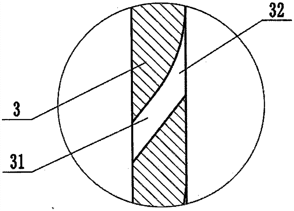
[0020] Such as figure 1 , figure 2 As shown, the improvement of the shakeout head of the new casting mold in this embodiment compared with the first embodiment is that the inner end of the jet hole 31 has a flared mouth 32 in the shape of a trumpet. The trumpet shape of the flared mouth 32 facilitates the airflow entering the jet hole 31 and reduces the injection resistance.
Embodiment 3
[0022] Such as figure 1 As shown, compared with the first embodiment, the improvement of the shakeout head of the new casting mold in this embodiment is that the air intake pipe 4 is a bendable and telescopic bellows structure. The intake pipe 4 is connected with the trachea, which can be properly bent and stretched to facilitate the installation of the trachea.
PUM
 Abstract
Description
Claims
Application Information
PatSnap Eureka turns technology decisions into work you can execute. Powered by our Innovation Knowledge Graph, it runs expert workflows across engineering, life sciences, materials and intellectual property. Get your review-ready output in minutes.


