
Fuel filler cap welder

A technology of oil filler cap and oil cap, which is applied in welding equipment, welding equipment, auxiliary welding equipment, etc., can solve the problems of low welding yield, welding deviation, and poor welding effect.

Active Publication Date: 2016-03-30
HERON INTELLIGENT EQUIP CO LTD
View PDF6 Cites 4 Cited by
  • Summary
  • Abstract
  • Description
  • Claims
  • Application Information

AI Technical Summary

Problems solved by technology

[0002] The traditional oil filler cap welding equipment mainly uses a single welding torch to weld the oil filler cap clockwise or counterclockwise for multiple times. Due to the sequential multiple welding, the fuel filler cap is easily deformed by heat during the welding process, and the final welding The finished product of the oil filler cap will be seriously deformed, and the expected welding purpose cannot be achieved, and the oil filler cap needs to be rotated to each welding position during the welding process, and the oil cap is prone to appear during the process of turning the oil filler cap Positioning offset with the support will eventually lead to welding deviation, welding failure or even welding deformation, low welding efficiency, poor welding effect, low welding yield and high cost

Method used


Image

  • Fuel filler cap welder
  • Fuel filler cap welder
  • Fuel filler cap welder

Examples


Embodiment Construction

[0021] In order to facilitate the understanding of the present invention, the present invention will be described more fully below with reference to the associated drawings. Preferred embodiments of the invention are shown in the accompanying drawings. However, the present invention can be embodied in many different forms and is not limited to the embodiments described herein. On the contrary, the purpose of providing these embodiments is to make the disclosure of the present invention more thorough and comprehensive.

[0022] Unless otherwise defined, all technical and scientific terms used herein have the same meaning as commonly understood by one of ordinary skill in the technical field of the invention. The terminology used herein in the description of the present invention is only for the purpose of describing specific embodiments, and is not intended to limit the present invention.

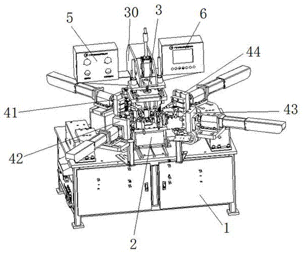
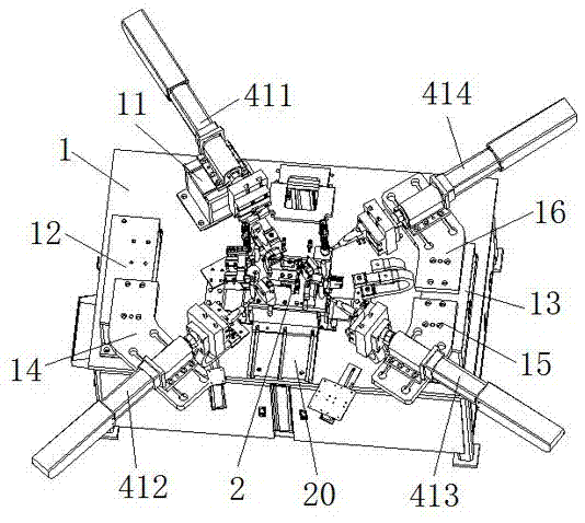
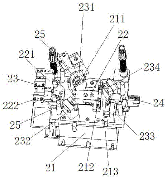
[0023] In this example, refer to Figure 1 to Figure 6As shown, the oil filler cap we...


PUM

PropertyMeasurementUnit
softening pointaaaaaaaaaa

Abstract

The invention discloses a fuel filler cap welder which comprises a machine table, a first welding set, a second welding set, a third welding set, a fourth welding set, an upper mould bracket, an upper mould set, an operation box and a display screen. According to the fuel filler cap welder, a fuel filler cap can be positioned by virtue of an upper mould, so that the fuel filler cap welder can be suitable for positioning fuel filler caps with different scale dimensions; a fuel cap bracket is subjected to positioning and fine turning by fixing a conductive electrode base by virtue of four fuel cap brackets , so that the fuel filler cap welder can be suitable for positioning the fuel cap brackets with different scale dimensions, and also can be suitable for positioning fuel cap rotary plates with different scale dimensions, and therefore, precise mould closing of the upper mould set and a lower mould set is realized; a plurality of welding guns can be used for simultaneously welding a fuel cap, so that the efficiency is high; a fuel filler cap welding workpiece is small in heating range, so that the fuel filler cap is small in deformation and even is not deformed, and therefore, a workpiece welding position is high in precision, a welding spot is free of an insufficient welding phenomenon, a welding spot is firm, a yield is high, a rate of defective products is lower than 1 / 10000, the cost is low, and the intelligent degree is high.

Description

technical field [0001] The invention relates to an oil filling port cover welding machine. Background technique [0002] The traditional oil filler cap welding equipment mainly uses a single welding torch to weld the oil filler cap clockwise or counterclockwise for multiple times. Due to the sequential multiple welding, the fuel filler cap is easily deformed by heat during the welding process, and the final welding The finished product of the oil filler cap will be seriously deformed, and the expected welding purpose cannot be achieved, and the oil filler cap needs to be rotated to each welding position during the welding process, and the oil cap is prone to appear during the process of turning the oil filler cap The positioning offset with the support will eventually lead to welding deviation, welding failure or even welding deformation. The welding efficiency is low, the welding effect is poor, the welding yield is low, and the cost is high. Therefore, in view of the shor...

Claims


Application Information

Patent Timeline
Patent Type & Authority Applications(China)
IPC IPC(8): B23K31/02B23K37/04
CPCB23K31/02B23K37/0443
Inventor 邹春芽
Owner HERON INTELLIGENT EQUIP CO LTD
Learn More