Injection mould

A technology of injection mold and injection column, applied in the field of plastic processing, can solve the problems of hardening, difference in molding quality, cooling of molten plastic, etc., and achieve the effect of prolonging service life, improving quality and reducing heat loss

Active Publication Date: 2016-03-30
浙江诺格汽车模具有限公司
View PDF2 Cites 3 Cited by
  • Summary
  • Abstract
  • Description
  • Claims
  • Application Information

AI Technical Summary

Problems solved by technology

For some small products, a single mold is often used for injection molding, although it can improve injection molding efficiency, and because all the cavities of this type of injection mold are injected through a single main injection runner, the main injection molding The runners are generally set close to all the cavities, but this will still cause the molten plastic entering the mold from the main injection runner to cool and gradually harden during the long-distance flow, resulting in product The shape quality is different between the side closer to the molten plastic inlet and the side farther from the molten plastic inlet

Method used


Image

  • Injection mould
  • Injection mould
  • Injection mould

Examples


Embodiment 1

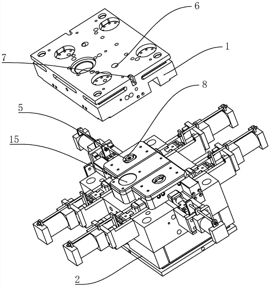
[0046] The head of the forming rod 11 is circular, and its cross-section is larger than the cross-section of the shaft of the forming rod 11, and at the same time, a cut about the diameter of the cross-section of the shaft is provided at the connection between the shaft and the head, and A chute 14 is provided on the piston 13, and the width of the slot of the chute 14 is the same as the thickness between the two notches. Therefore, the forming rod 11 can slide into the sliding groove 14, and it will not move in its own axial direction, thus realizing the detachable function.

Embodiment 2

[0048] The rod head of the forming rod 11 is provided with an external thread, and the piston 13 is provided with an internal thread, and the detachable connection between the forming rod 11 and the piston 13 is realized through the threaded cooperation of the two.

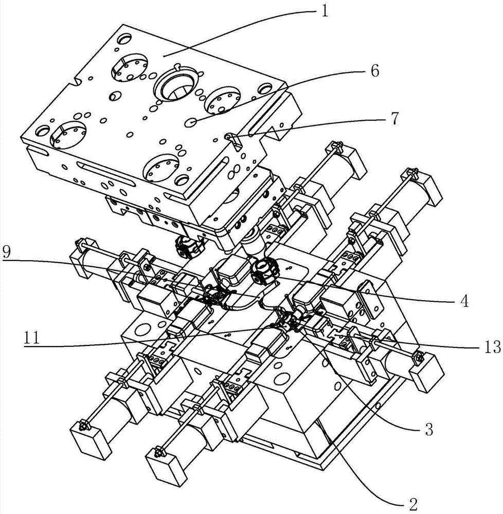
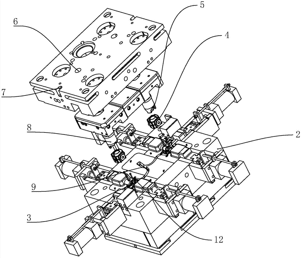
[0049] The fixed mold core 3 is provided with a fixed needle 12 for fixing the column sleeve 8 . The number of the fixed needles 12 can be determined according to the specific situation. Here, the number of the fixed needles 12 is two and the diameter of the injection column 5 is relatively symmetrical , and the needle head of the fixed needle 12 is in contact with the forming rod 11 .

[0050] On the one hand, the fixing needle 12 can effectively fix the column sleeve 8, and on the other hand, the fixing needle 12 is in contact with the molding rod 11, so as to improve the limiting effect on the fixing rod and prevent the molten plastic from punching out of the injection molding column. 5, the forming rod 11 will...


PUM


Abstract

The invention discloses an injection mould. The injection mould comprises a fixed mould and a movable mould, wherein a plurality of movable mould cores are arranged on the movable mould; fixed mould cores which are matched with the movable mould cores are embedded into the fixed mould; an injection molding column is arranged on the top of each fixed mould core in a penetration mode; a column sleeve is arranged on the corresponding injection molding column in a sleeving mode; injection molding holes which correspond to the corresponding injection molding columns are formed in the fixed mould; an injection molding runner which is communicated with each mould core is arranged on the movable mould; and all injection molding runners are gathered on the same point. According to the injection mould, the injection molding column is arranged on each fixed mould core in the penetration mode, and therefore, during casting of each product, molten plastic can be directly injected into a mould cavity from a plastic container, so that a flow distance of a formed body plastic of each product is reduced, and therefore, heat loss when the former body plastic is unstable is reduced, and the products can be more uniform after being formed; and the injection molding runners are gathered at one point, so that the formed products are connected together, and therefore, an operator conveniently takes out the products.

Description

technical field [0001] The present invention relates to the field of plastic processing, in particular to an injection mold. Background technique [0002] Injection mold is a tool for producing plastic products; it is also a tool for giving plastic products complete structure and precise dimensions. For some small products, a single mold is often used for injection molding, although the injection molding efficiency can be improved, and this kind of injection mold has all the cavities injected through a single main injection runner, so the main injection molding The runner is generally set at a position close to all the cavities, but this will still cause the molten plastic entering the mold from the main injection runner to cool and gradually harden during the long-distance flow process, resulting in the product. The molding quality of the side closer to the molten plastic inlet is different from that of the side farther from the molten plastic inlet. SUMMARY OF THE INVEN...

Claims


Application Information

Patent Timeline
Patent Type & Authority Applications(China)
IPC IPC(8): B29C45/26B29C45/27B29C45/32
CPCB29C45/2602B29C45/2669B29C45/2708B29C45/32B29C2045/2671
Inventor 杨鸥
Owner 浙江诺格汽车模具有限公司
Why Eureka
Try Eureka