
Motor carrier conveying device

A technology for conveying devices and vehicles, applied in conveyors, transportation and packaging, etc., can solve problems such as low efficiency and achieve high efficiency

Active Publication Date: 2016-03-30
BOZHON PRECISION IND TECH CO LTD
View PDF3 Cites 3 Cited by
  • Summary
  • Abstract
  • Description
  • Claims
  • Application Information

AI Technical Summary

Problems solved by technology

[0002] With the development of economy and technology, the use of automation equipment in industrial production is becoming more and more extensive. In the production line of air conditioners, the motor needs to be assembled. The motor is placed in the motor carrier by the manipulator, and the motor carrier passes through the motor The carrier conveying device is used for conveying, the traditional motor carrier conveying device can only move in a single station, and the efficiency is low

Method used


Image

  • Motor carrier conveying device
  • Motor carrier conveying device
  • Motor carrier conveying device

Examples


Embodiment Construction

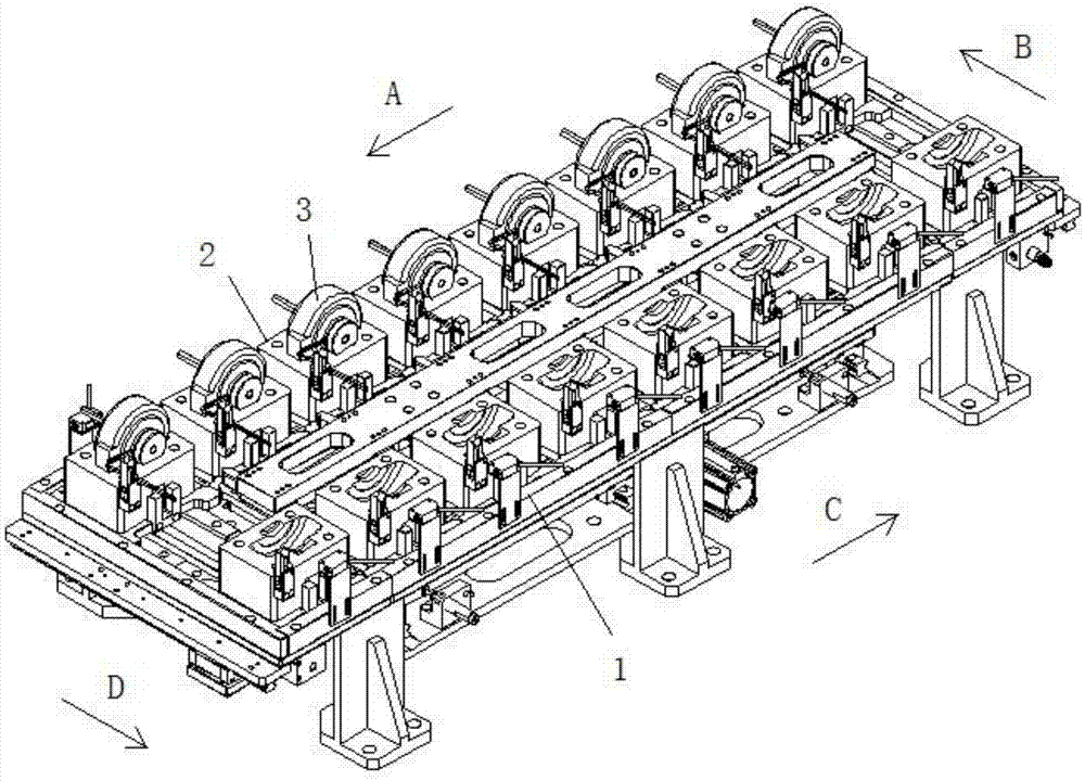
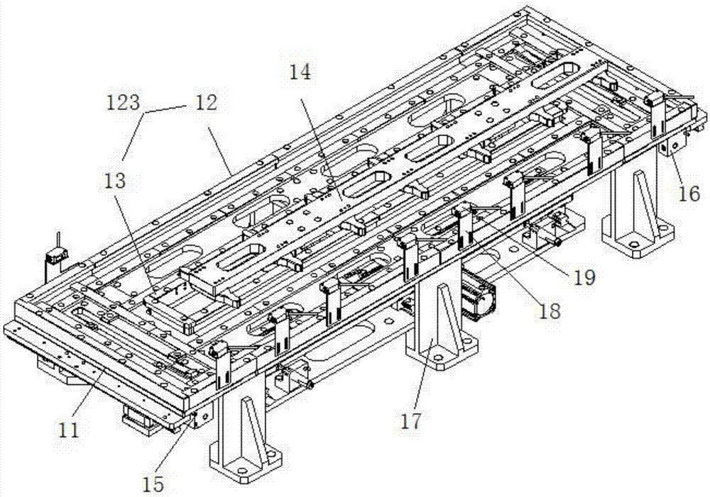
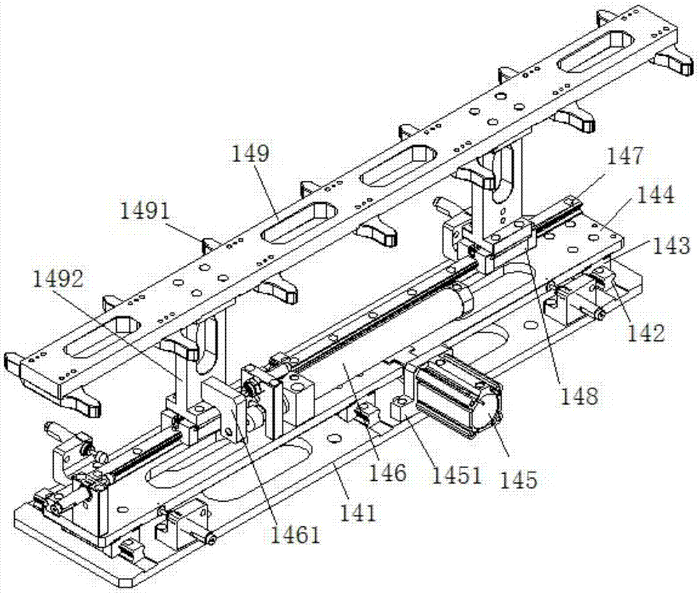
[0021] see Figure 1 to Figure 5 , motor carrier conveying device 1, comprises track mounting plate 11, outer track 12 and inner track 13 that are positioned on track mounting plate 11, outer track 12 and inner track 13 are rectangular, and inner track 13 is positioned at the space that outer track 12 closes The inner and outer tracks 12 and the inner track 13 together form a rectangular delivery track 123, on which a plurality of motor carriers 2 are arranged, the motors 3 are placed in the motor carrier 2, and the motor carriers 2 run along the rectangular delivery track 123 The motor carrier conveying device 1 also includes a shift fork assembly 14 and a first push assembly 15 and a second push assembly 16 located on both sides of the shift fork assembly. The first push assembly 15 and the second push assembly 16 have the same structure and are related to the The center of the conveying track is distributed symmetrically, and the first pushing assembly 15 and the second pus...


PUM


Abstract

The invention discloses a motor carrier conveying device which comprises a rail mounting plate and a conveying rail positioned on the rail mounting plate, and further comprises a shifting fork assembly for transversely moving a motor carrier along the conveying rail as well as a first pushing assembly and a second pushing assembly for longitudinally moving the motor carrier along the conveying rail. The conveying rail is rectangular; the first pushing assembly, the second pushing assembly and the shifting fork assembly co-drive the motor carrier to operate along the conveying rail; the shifting fork assembly comprises a shifting fork fixing plate capable of transversely and longitudinally moving; and a plurality of shifting forks which are distributed transversely at an equal distance are symmetrically arranged at the two sides of the shifting fork fixing plate. According to the motor carrier conveying device, the shifting fork assembly drives the motor carrier to transversely move, and the first pushing assembly and the second pushing assembly drive the motor carrier to longitudinally move, so that the motor carrier operates in the rectangular conveying rail; and multiple motor carriers are simultaneously moved by utilizing the multiple shifting forks, so that the efficiency is high.

Description

technical field [0001] The invention relates to the field of automation equipment, in particular to a motor carrier conveying device. Background technique [0002] With the development of economy and technology, the use of automation equipment in industrial production is becoming more and more extensive. In the production line of air conditioners, the motor needs to be assembled. The motor is placed in the motor carrier by the manipulator, and the motor carrier passes through the motor The carrier conveying device is used for conveying. The traditional motor carrier conveying device can only move at a single station, and the efficiency is low. [0003] Therefore, it is necessary to provide a novel motor carrier conveying device to solve the above problems. Contents of the invention [0004] The object of the present invention is to provide a high-efficiency motor carrier conveying device. [0005] The present invention realizes above-mentioned purpose through following t...

Claims


Application Information

Patent Timeline
Patent Type & Authority Applications(China)
IPC IPC(8): B65G25/02
CPCB65G25/02B65G2201/02
Inventor 吕绍林杨愉强吴小平贺鹏史成浩赵守众
Owner BOZHON PRECISION IND TECH CO LTD
Learn More