A kind of oblique angle tongue-and-groove building formwork

A construction formwork and groove-and-groove technology, which is applied in the field of oblique angle-and-groove construction formwork, can solve the problems of high connection strength, fast connection speed, and limited installation space of building formwork, achieving high connection strength, improving construction efficiency, and stress strength balanced effect

Active Publication Date: 2018-05-04
NENGCHENG GRP
View PDF10 Cites 0 Cited by
  • Summary
  • Abstract
  • Description
  • Claims
  • Application Information

AI Technical Summary

Problems solved by technology

[0003] For this reason, the technical problem to be solved by the present invention lies in the problem that the installation of building templates in the prior art is limited by space; Easy disassembly and assembly, high-strength building formwork

Method used


Image

  • A kind of oblique angle tongue-and-groove building formwork
  • A kind of oblique angle tongue-and-groove building formwork
  • A kind of oblique angle tongue-and-groove building formwork

Examples


Embodiment 1

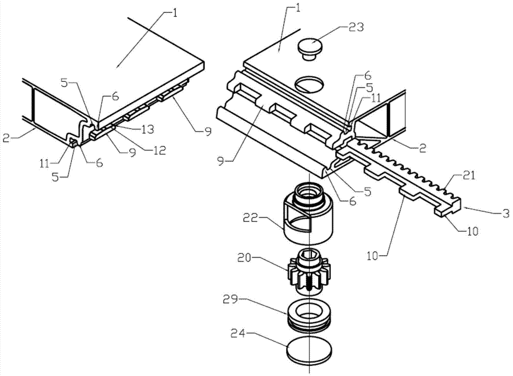
[0057] Such as Figure 1-5 As shown, a beveled tongue and groove building formwork of this embodiment has

[0058] A pouring surface 1 and an outer surface 2 opposite to the pouring surface 1;

[0059] A groove-and-groove structure, formed on the connecting edge between the pouring surface 1 and the outer surface 2, the groove-and-groove structure includes a fitting structure, and the fitting structure is suitable for combining with the edge and the two sides The pouring surface 1 of one of the building formwork forms an included angle, and the movement in the direction of embedding movement is embedded with the adjacent building formwork. and separation in the direction of the embedding movement direction; and

[0060] The locking structure includes a locking piece 3 that is movably and immovably arranged on the edge in the direction of embedding movement, and a locking surface 4 that is set on the corresponding edge of the adjacent template. The locking piece 3 is molded o...

Embodiment 2

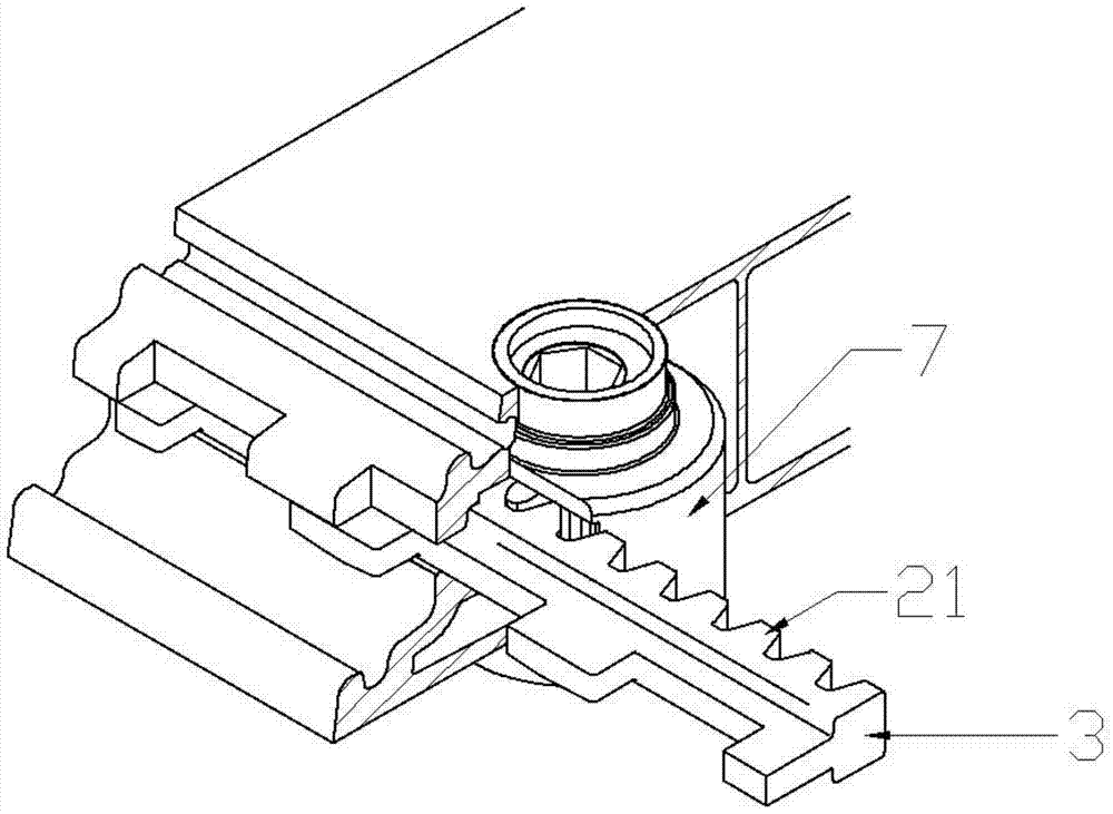
[0072] Such as Figure 6 and 7 As shown, the difference between this embodiment 2 and embodiment 1 lies in the formation of the locking surface 4, the shape of the slot, and the structure of the locking member 3. In this embodiment 2, the locking surface 4 is formed on the corresponding Adjacent to the groove on the edge of the building formwork, the locking member 3 is composed of the split locking part 10 and the driving part 14, and at least one transmission structure arranged between the locking part 10 and the driving part 14 The driving mechanism 7 drives the driving part 14 to slide along the direction of the edge extension, the driving structure drives the locking part 10 to extend into or withdraw from the locking surface 4, and the shape of the slot is suitable for Keep the driving part 14 fixed to slide along the edge extending direction, and the locking part 10 moves to the locking direction of the locking surface 4 on the adjacent building formwork.

[0073] In ...

Embodiment 3

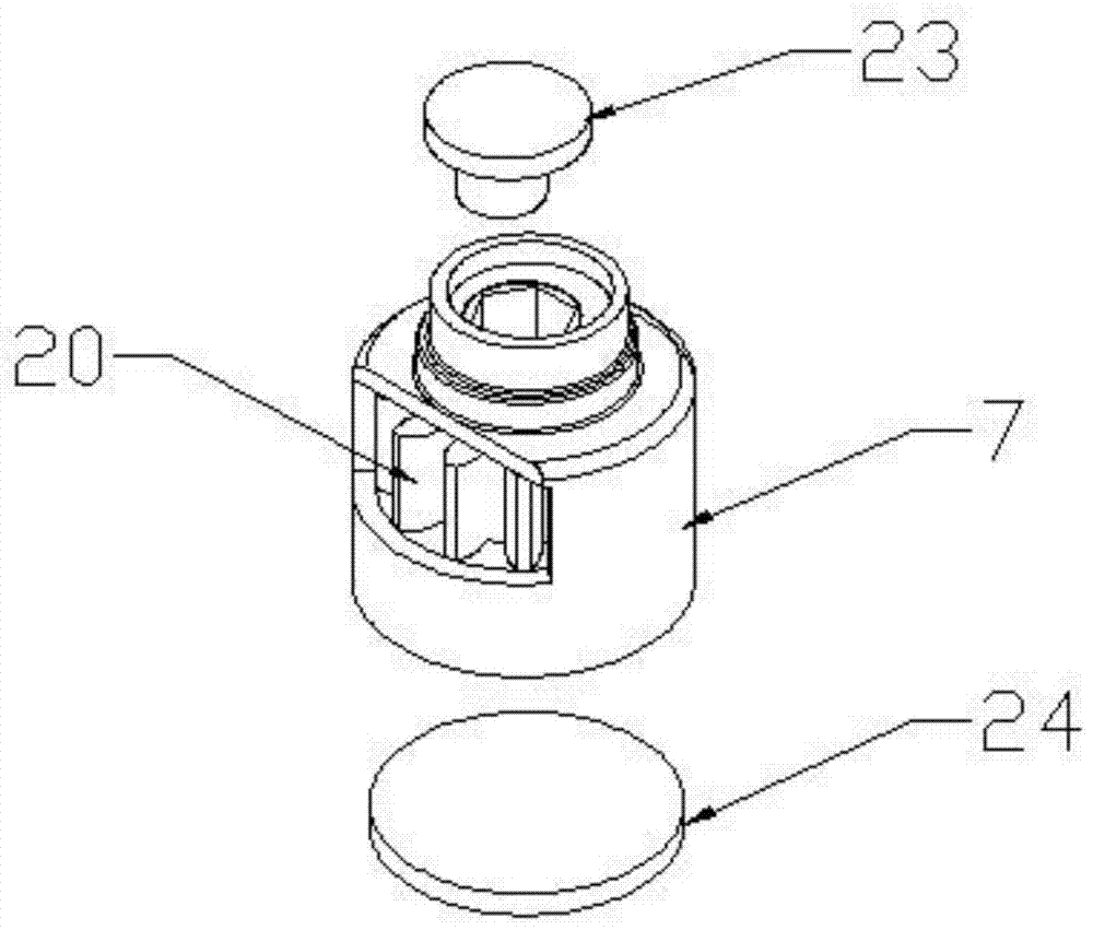
[0076] Such as Figure 8 As shown, the difference between this embodiment 3 and embodiment 1 is that the locking surface 4 is a groove formed on the edge of the adjacent building formwork, and the driving mechanism 7 drives the locking member 3 to extend along the edge direction while moving towards the locking surface 4 of the adjacent building formwork, a guide structure is also provided between the locking piece 3 and the building formwork where the locking piece 3 is located, and the guiding structure is opposite to the locking piece 3 The guide is moved in the direction of said locking face 4 of the adjacent building formwork. The toggle member is a gear 20, the rotating shaft of the gear 20 is arranged perpendicular to the edge; the toggled structure is a fan-shaped rack 30 formed on the locking member 3; the guide structure includes a molded The second guide groove 17 on the locking member 3, and one end is connected on the building template, and the other end passes t...


PUM


Abstract

The invention relates to a beveled groove-and-groove building formwork, which has a pouring surface and an outer surface; the fitting structure is suitable for moving in an embedding movement direction at an included angle with the edge and the pouring surface of one of the building formworks that are joined together. Embedded with the adjacent building formwork, the fitting structure limits the separation of the edge and the opposite edge of the adjacent building formwork in a direction perpendicular to the edge and the direction of embedding movement; the locking structure includes a locking piece that can be arranged on the edge, and on the adjacent The locking surface provided on the corresponding edge of the formwork; in the unlocked state, the movement between the locking part of the locking part and the locking surface on the adjacent formwork in the embedded movement direction does not interfere with each other; and after the two adjacent building formworks are matched, Through the action of the locking part, the locking part and the corresponding locking surface on the adjacent formwork are engaged with each other to lock the two adjacent building formworks in the embedding movement direction. The construction formwork of the present invention is not only fast and convenient to assemble and disassemble, but also has high connection strength, and the joint strength is not lower than that of a whole formwork.

Description

technical field [0001] The invention relates to the field of construction, in particular to a beveled tongue-and-groove building formwork. Background technique [0002] The existing building formwork usually adopts a detachable connection method, and small pieces of formwork are assembled into the required modeling shape on site. One of the assembling and connecting methods is to set connecting holes on the non-casting surface of the formwork, use bolts to connect, or set connecting flanges, and use a quick clamping mechanism to realize the connection. There is also the use of tongue-and-groove joint structures on the opposite edges of the formwork connection for connection. The usual way of bolt connection and clamping mechanism connection needs to set at least two bolts or clamping mechanisms on the connecting edge of the formwork, and at the same time needs to perform leveling work on the pouring surface, which makes its work efficiency low and the flatness of the pourin...

Claims


Application Information

Patent Timeline
Patent Type & Authority Patents(China)
IPC IPC(8): E04G9/02E04G17/075
Inventor 王斌坚章国荣
Owner NENGCHENG GRP
Why Eureka
Try Eureka