Installation device and method of U-shaped beam in shield type TBM

A technology of installation device and installation method, which is applied in shaft equipment, earthwork drilling, wellbore lining, etc., and can solve the problem that U-shaped beams cannot be tightly attached to the cave wall, joints are not firmly connected, and the curvature of U-shaped beam installers and excavation holes Problems such as wall mismatch can be solved to achieve the effect of improving tunneling efficiency, improving installation efficiency, and ensuring installation accuracy

Active Publication Date: 2016-03-30
中国葛洲坝集团第三工程有限公司
View PDF6 Cites 1 Cited by
  • Summary
  • Abstract
  • Description
  • Claims
  • Application Information

AI Technical Summary

Problems solved by technology

[0003] The purpose of the present invention is to provide a U-shaped beam installation device and method in a shield-type TBM to solve the problem that the arc of the U-beam installer in the shield-type TBM does not match the excavation wall. The present invention can solve the problem of TBM installation The mismatch between the U-shaped beam and the excavated wall causes the problem that the U-shaped beam cannot be tightly attached to the wall and the joint connection is not firm. It can significantly improve the stress state of the U-shaped beam and give full play to its supporting performance; at the same time, it can effectively improve the U-shaped beam. installation efficiency, thereby improving the tunneling efficiency of TBM

Method used


Image

  • Installation device and method of U-shaped beam in shield type TBM
  • Installation device and method of U-shaped beam in shield type TBM

Examples


Embodiment Construction

[0026] Below in conjunction with accompanying drawing, the present invention is described in further detail:

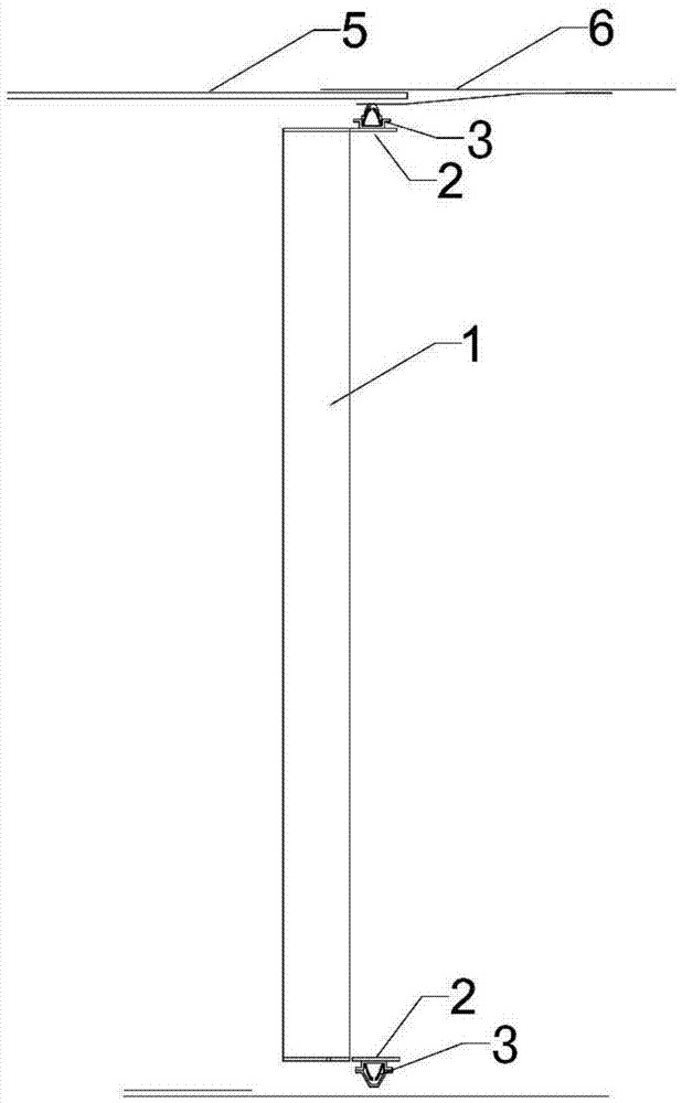
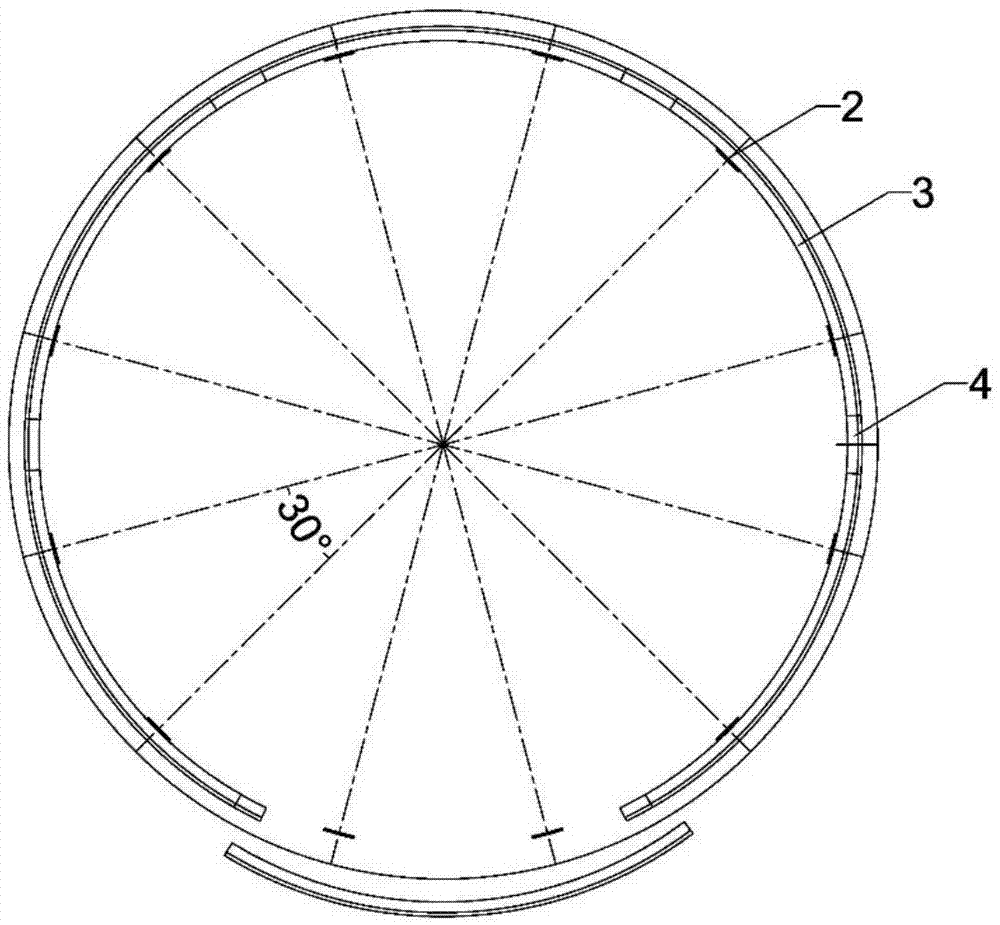
[0027] see Figure 1 to Figure 2 , a U-shaped beam installation device in a shield-type TBM, including a U-shaped beam installer 1 arranged in a tunnel, and a protective shield 5 is provided between the U-shaped beam installer 1 and the surrounding rock excavation wall 6 at the top of the tunnel , the U-shaped beam installer 1 is cylindrical, and twelve arc-shaped steel plates 2 are welded and fixed on the outer edge of the U-shaped beam installer 1, and the two ends of each arc-shaped steel plate 2 are connected with the center of curvature The included angles are all 30°, the curved steel plate 2 forms a cylinder whose radius of curvature is equal to the outer diameter of the U-shaped beam installer 1, and the outer side of the curved steel plate 2 is provided with six U-shaped beams 3, and the adjacent U-shaped beams 3 The profile beams 3 are connected by joints 4...


PUM


Abstract

The invention discloses an installation device and method of a U-shaped beam in a shield type TBM. The installation device comprises a U-shaped beam installer which is arranged in a tunnel and is shaped like a cylinder, multiple arc-shaped steel plates are fixed on the outer edge of the U-shaped beam installer, the arc-shaped steel plates form a cylinder of which the curvature radius is equal to the outer diameter of the U-shaped beam installer, multiple U-shaped beams are arranged on the outer side of each arc-shaped steel plate, and the adjacent U-shaped beams are connected through connectors. According to the installation device and method of the U-shaped beam in the shield type TBM, the problems that due to the fact that the TBM installer is not matched with an excavation tunnel wall, the U-shaped beams can not be tightly attached to the tunnel wall, and connection of the connectors is not firm can be solved, the stress state of the U-shaped beams can be obviously improved, and the supporting performance of the U-shaped beams is fully exerted; meanwhile, the installation efficiency of the U-shaped beams can be effectively improved, and the excavation efficiency of the TBM is further improved.

Description

technical field [0001] The invention relates to a TBM tunnel support technology, in particular to a U-shaped beam installation device and method in a shield-type TBM. Background technique [0002] The TBM tunnel construction method has been widely used in the construction of hydropower diversion tunnels and highway-railway tunnels due to its advantages of fast construction speed and low dust in the construction environment. During the TBM construction process, as the cutter head continues to drive forward, the excavation surface is continuously exposed from behind the TBM shield. At this time, a support operation needs to be carried out in the exposed area of ​​the surrounding rock. The primary support efficiency is not only related to the stability of the surrounding rock and the safety of personnel, but also directly affects the tunneling speed of the TBM. Now the U-beam installer of the shield-type TBM is located inside the shield, and the assembly of the U-beam is perfo...

Claims


Application Information

Patent Timeline
Patent Type & Authority Applications(China)
IPC IPC(8): E21D11/18E21D9/06
CPCE21D9/06E21D11/18E21D11/183
Inventor 柳同祥王西奎朱则浩何敏付海亮崔健张辉宣云舒王剑路飞韦国代兴艳李志强刘章夏永忠
Owner 中国葛洲坝集团第三工程有限公司
Why Eureka
Try Eureka