One-way valve for die clamper

A technology of one-way valves and mold clamps, applied in the direction of control valves, valve devices, functional valve types, etc., can solve the problems of mold shifting, falling, etc., and achieve the effect of simple structure and convenient assembly

Inactive Publication Date: 2016-03-30
苏州格莱富机械科技有限公司
View PDF7 Cites 1 Cited by
  • Summary
  • Abstract
  • Description
  • Claims
  • Application Information

AI Technical Summary

Problems solved by technology

[0002] As an important part of the quick mold change system, the mold clamp is used to clamp and fix the mold. After the mold clamp clamps the mold, in order to ensure that the mold is clamped and does not fall, the air pump unit is required to continuously provide The pressure is as high as 250Kg / cm2, but when there is a power failure or other abnormalities that lead to sudden gas failure, the mold clamp will loosen the pressure plate due to the loss of pressure, causing the mold to shift or even fall

Method used


Image

  • One-way valve for die clamper

Examples


Embodiment Construction

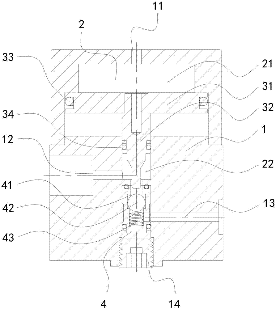
[0012] The present invention will be further described below in conjunction with the accompanying drawings and specific embodiments.

[0013] Such as figure 1 As shown, the one-way valve used for the mold clamp includes a valve body 1, and a valve cavity 2 is arranged in the valve body 1, including a first valve cavity 21 and a second valve cavity 22, and the top of the valve body 1 is provided with a communication channel A gas channel 11 of a valve cavity 21, the first valve cavity 21 is provided with a piston 31 and a piston rod 32 connected to the piston 31, the piston rod 32 is slidingly fitted with the valve body 1, and the piston rod 32 is in sealing connection with the second valve cavity 22 The second valve cavity 22 is provided with a steel ball seat 4, and the steel ball seat 4 is provided with a fluid channel 41 communicating with the second valve cavity 22, and the fluid channel 41 is provided with a steel ball 42 and a spring 43, and one end of the spring 43 lean...


PUM


Abstract

The invention discloses a one-way valve for a die clamper. The one-way valve comprises a valve body. A valve cavity is formed in the valve body and comprises a first valve cavity body and a second valve cavity body. A gas channel communicated with the first valve cavity body is arranged at the top of the valve body. A piston and a piston rod connected with the piston are arranged in the first valve cavity body. The piston rod is in sliding fit with the valve body. A steel ball seat is arranged in the second valve cavity body. A fluid channel is formed in the steel ball seat. A steel ball and a spring are arranged in the fluid channel. The oil inflow end of the fluid channel is sealed through the steel ball. An oil inflow channel is arranged on one side of the valve body. An oil outflow channel is arranged on the other side of the valve body. When the piston slides towards the steel ball, one end of the piston rod pushes the steel ball to be away from the oil inflow end of the fluid channel; when the one-way valve works normally, oil flows in through the oil inflow channel, passes the fluid channel and flows out of the oil outflow channel; and when an abnormal condition occurs and no oil flows in, the fluid channel is sealed through the steel ball, the oil cannot flow to the oil inflow channel through the oil outflow channel, and the pressure maintenance effect is achieved.

Description

technical field [0001] The invention relates to the field of quick mold change systems, in particular to a check valve for a mold clamp. Background technique [0002] As an important part of the quick mold change system, the mold clamp is used to clamp and fix the mold. After the mold clamp clamps the mold, in order to ensure that the mold is clamped and does not fall, the air pump unit is required to continuously provide The pressure is as high as 250Kg / cm2, but when there is a power failure or other abnormalities that lead to sudden gas failure, the clamp will loosen the pressure plate due to the loss of pressure, causing the mold to shift or even fall. Contents of the invention [0003] The technical problem to be solved by the present invention is to provide a one-way valve for a mold clamp with a function of maintaining pressure. [0004] The technical solution adopted by the present invention to solve the technical problem is: the one-way valve used for the mold cla...

Claims


Application Information

Patent Timeline
Patent Type & Authority Applications(China)
IPC IPC(8): F16K15/18
CPCF16K15/1823
Inventor 管高峰田进
Owner 苏州格莱富机械科技有限公司
Why Eureka
Try Eureka