Device for testing mechanical response of surrounding rock and anchoring body under action of dynamic load and static load

A technology of mechanical response and test equipment, applied in the direction of measuring equipment, scientific instruments, instruments, etc., can solve problems such as limited support, cognitive deviation, and inability to simulate rockburst induced by dynamic impact

Active Publication Date: 2016-03-30
INST OF ROCK & SOIL MECHANICS CHINESE ACAD OF SCI
View PDF7 Cites 13 Cited by
  • Summary
  • Abstract
  • Description
  • Claims
  • Application Information

AI Technical Summary

Problems solved by technology

However, the theory of bolt design is still not perfect, and the design of bolts still relies on experience. The key reason is that the mechanism and effect evaluation of the toughening and cracking arrest of bolts still lack reliable experimental basis. The triaxial or biaxial tests of the anchor reinforcement are far from the actual stress state of the anchor, resulting in a deviation in the understanding of the anchor failure mechanism and the evaluation of the anchor support effect, which leads to the establishment of the anchor failure model. Does not match the actual project
[0004] In addition to surrounding rock rupture, dynamic impact damage (such as rockburst) is the most severe and destructive form of disaster in underground engineering. However, there are still no effective means to reveal its disaster-causing mechanism and the anti-shock working mechanism of bolt support. , the current rockburst simulation test is still based on the static load compression or sudden unloading test of the rock block, which cannot simulate the process of rockburst induced by dynamic impact. The existing bolt impact test is still an extension of the bolt static load pullout test. , which is far from the actual working environment of the bolt, and the supporting effect of the test results is limited

Method used


Image

  • Device for testing mechanical response of surrounding rock and anchoring body under action of dynamic load and static load
  • Device for testing mechanical response of surrounding rock and anchoring body under action of dynamic load and static load
  • Device for testing mechanical response of surrounding rock and anchoring body under action of dynamic load and static load

Examples


Embodiment 1

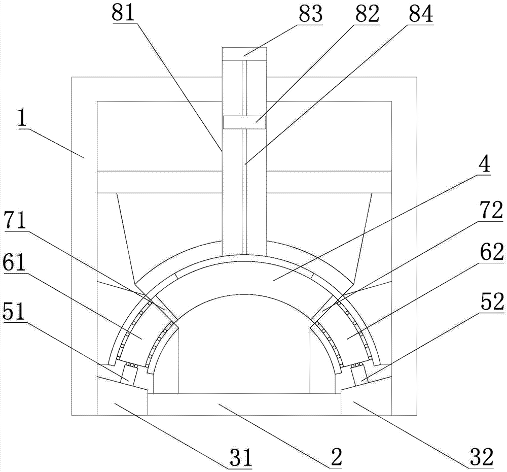
[0036] Such as Figure 1-3 As shown, the test device for the mechanical response of surrounding rock and anchorage under dynamic and static loads includes a frame 1 and an arc-shaped channel located in the frame 1. The bottom of the frame 1 is provided with a bottom support plate 21, and the arc-shaped The channel includes a sample channel 4 located in the middle of the arc and a left channel and a right channel located on the left and right sides of the sample channel 4. A sample 12 can be placed in the sample channel 4, and the sample 12 is The arch is installed between the left pad 71 and the right pad 72, and between the bottom support plate 21 is the hollow area 2 where the anchor rod 13 can be arranged, and the top limit plate is provided above the sample channel 4, and the top An impact load loading device is provided above the outer side of the limiting plate, and the impact load loading device provides a top-down impact load on the top of the top limiting plate, and t...

Embodiment 2

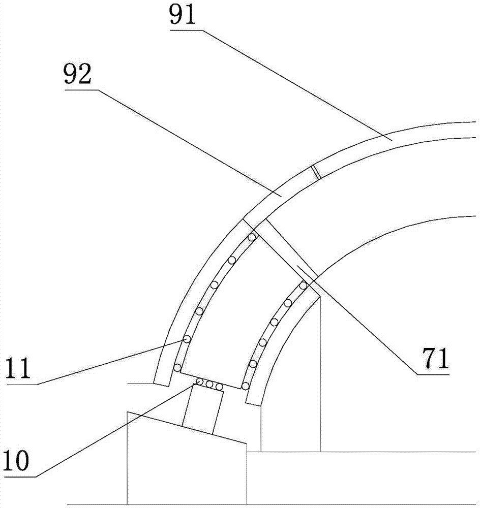
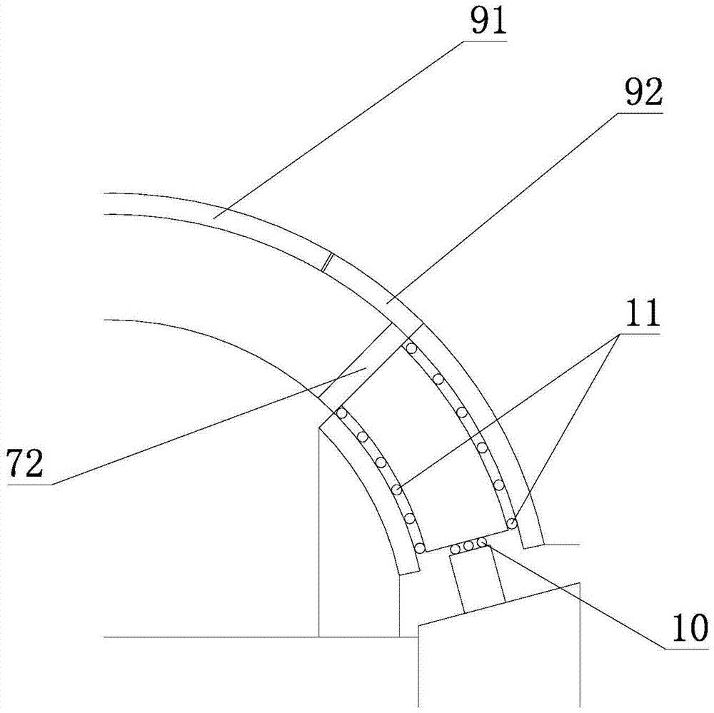
[0047] Such as Figure 4 As shown, on the basis of Example 1, the sample 12 is equipped with three anchor rods 13 according to the test plan, the upper surface of the left bearing plate 31 is parallel to the lower surface of the left force transmission plate 61, and the above two A left loading device is arranged between the surfaces, and the direction of the force exerted by the left loading device on the left force transmission plate is along the tangential direction of the left channel. Similarly, the upper surface of the right bearing plate 32 and the lower surface of the right force transmission plate 62 The surfaces are parallel, and a right loading device is arranged between the above two surfaces, and the direction of the force exerted by the right loading device on the right force transmission plate is along the tangential direction of the right channel.


PUM


Abstract

The invention relates to a device for testing the mechanical response of surrounding rock and an anchoring body under the action of a dynamic load and a static load. The device comprises a frame and an arc-shaped channel located in the frame, wherein a lower support plate used for supporting the arc-shaped channel is arranged under the arc-shaped channel, and the lower end of the lower support plate is connected with a bottom support plate; the arc-shaped channel comprises a sample channel body located in the middle of the arc, a left channel body and a right channel body, the left channel body and the right channel body are located on the left side and right side of the sample channel body, a top end limiting plate is arranged above the sample channel body, an impact load loading device is arranged on the outer side of the top end limiting plate, a left force transmission plate and a right force transmission plate are arranged in the left channel body and the right channel body respectively, the right end of the left force transmission plate and the left end of the right force transmission plate are connected with the left end and right end of the sample channel body respectively, and the left end of the left force transmission plate and the right end of the right force transmission plate are connected with a left loading device and a right loading device respectively. By the adoption of the device, the practical working environment of the surrounding rock and the anchoring body can be accurately simulated, and the processes of fracture evolution of the surrounding rock and the anchoring body under the action of the dynamic load and the static load can be directly observed and tested.

Description

technical field [0001] The invention relates to a test device for the mechanical response of surrounding rock and anchorage under dynamic and static loads. Background technique [0002] After the excavation of rock underground engineering, the tangential stress of the surrounding rock of the tunnel wall increases, the radial stress decreases, and the increase of the stress difference leads to the failure of the surrounding rock. Due to the complexity of the rock mass medium, the evolution process of the surrounding rock fracture in different parts of the tunnel is not yet clear. Due to the influence of complex geological conditions and interference from construction factors, the field test technology is still unable to reveal this problem well, and the objects of indoor conventional triaxial and true triaxial tests are only relatively small cubes with uniform stress state. Some model tests also focus on full-scale tunnel excavation, making it difficult to observe the failure...

Claims


Application Information

Patent Timeline
Patent Type & Authority Applications(China)
IPC IPC(8): G01N3/00
Inventor 张传庆崔国建周辉胡大伟朱勇
Owner INST OF ROCK & SOIL MECHANICS CHINESE ACAD OF SCI
Why Eureka
Try Eureka