
Discharge circuit for preventing voltages of batteries from flowing backwards and control method

A discharge circuit and battery voltage technology, applied in battery circuit devices, safety/protection battery circuits, charge equalization circuits, etc., can solve problems such as potential safety hazards and inability to discharge in time, so as to improve safety, avoid excessive discharge, and prevent battery The effect of voltage backfeeding

Inactive Publication Date: 2016-03-30
XIAN TGOOD INTELLIGENT CHARGING TECH CO LTD
View PDF4 Cites 1 Cited by
  • Summary
  • Abstract
  • Description
  • Claims
  • Application Information

AI Technical Summary

Problems solved by technology

[0003] The purpose of the present invention is to overcome the above disadvantages, provide a discharge circuit and control method for preventing battery voltage backfilling, and solve the problem in the prior art that when the high-voltage DC unit is disconnected from the system, it cannot be discharged in time, causing potential safety hazards

Method used


Image

  • Discharge circuit for preventing voltages of batteries from flowing backwards and control method
  • Discharge circuit for preventing voltages of batteries from flowing backwards and control method
  • Discharge circuit for preventing voltages of batteries from flowing backwards and control method

Examples


Embodiment 1

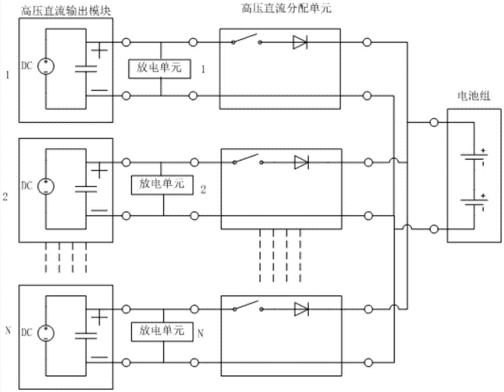
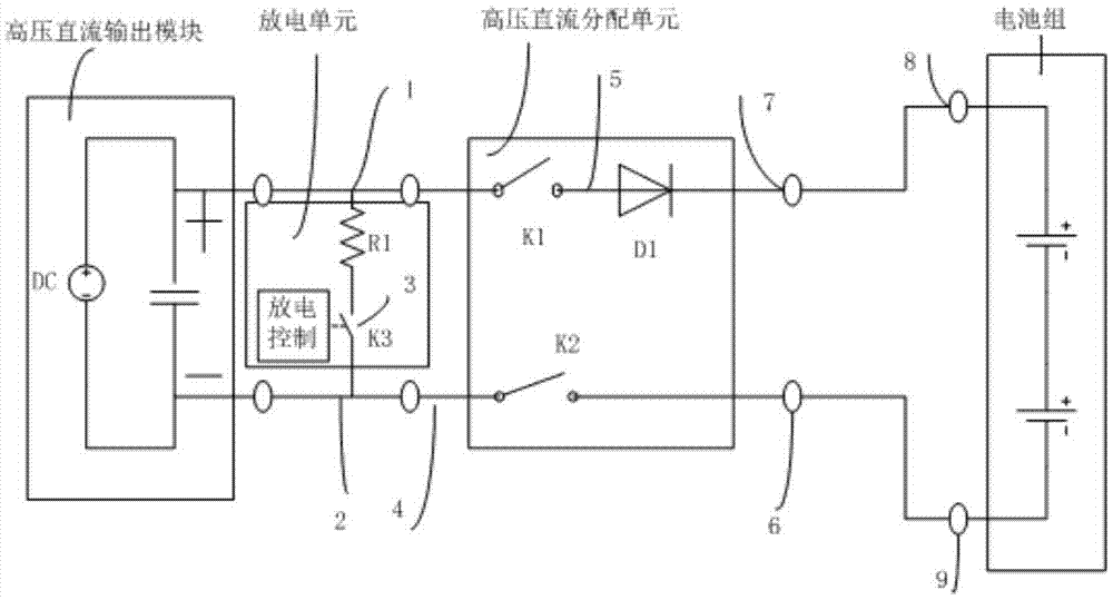
[0026] see figure 1 and figure 2 , a discharge circuit for preventing battery voltage backfeeding, comprising at least one high-voltage direct current output module with positive and negative poles, each high-voltage direct-current output module is connected to its corresponding high-voltage direct-current distribution unit, and the high-voltage direct-current output module and the high-voltage direct-current distribution unit are connected Discharge units are connected in parallel, and all high-voltage DC distribution units are connected to battery packs;

[0027] The discharge unit includes a power resistor R1 and a discharge switch K3 connected in series, the power resistor R1 is connected to the positive pole of the high-voltage DC output module, and the other end of the discharge switch K3 is connected to the negative pole of the high-voltage DC output module;

[0028] The high-voltage DC distribution unit includes a first switch K1 connected to the positive pole of the...

Embodiment 2

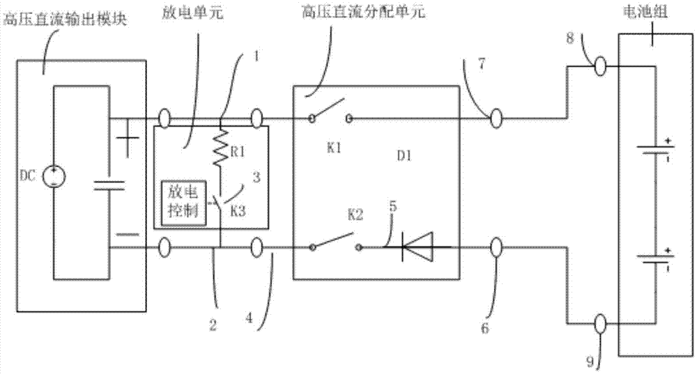
[0030] see image 3 , a discharge circuit for preventing battery voltage backfeeding, comprising at least one high-voltage direct current output module with positive and negative poles, each high-voltage direct-current output module is connected to its corresponding high-voltage direct-current distribution unit, and the high-voltage direct-current output module and the high-voltage direct-current distribution unit are connected Discharge units are connected in parallel, and all high-voltage DC distribution units are connected to battery packs;

[0031] The discharge unit includes a power resistor R1 and a discharge switch K3 connected in series, the power resistor R1 is connected to the positive pole of the high-voltage DC output module, and the other end of the discharge switch K3 is connected to the negative pole of the high-voltage DC output module;

[0032] The high-voltage direct current distribution unit includes a first switch K1 connected to the positive pole of the hi...


PUM


Abstract

The invention discloses a discharge circuit for preventing voltages of batteries from flowing backwards and a control method. The discharge circuit comprises a high-voltage direct current output module with a positive electrode and a negative electrode, wherein each high-voltage direct current output module is connected with a corresponding high-voltage direct current distribution unit; a discharge unit is connected between each high-voltage direct current output module and each high-voltage direct current distribution unit in parallel; a first switch K1 and a second switch K2 are arranged on the positive electrode and the negative electrode of each high-voltage direct current distribution unit respectively; the first switch K1 or the second switch K2 is connected with a diode D1 or a diode D2 in series; the negative electrode of the diode D1 is connected with the positive electrode of a battery pack; the positive electrode of the diode D2 is connected with the negative electrode of the battery pack; all high-voltage direct current distribution units all are connected with the battery pack; when a system does not charge a load or the batteries, the voltages of the batteries cannot flow back to input ends due to presence of the diode D1 or the diode D2; and meanwhile, the high-voltage direct current output modules are controlled to be shut down, so that over-zero separation of the high-voltage direct current distribution units K1 and K2 can be achieved; and damage to a device caused by high-voltage and high-current arc discharge is avoided.

Description

【Technical field】 [0001] The invention belongs to the field of power electronics, and in particular relates to a discharge circuit and a control method for preventing battery voltage backfilling. 【Background technique】 [0002] With the development of power electronics technology, high-voltage DC technology is widely used in various occasions, especially in the charging of electric vehicles. High-voltage direct current technology has the characteristics of high transmission efficiency, mature parallel technology, and high reliability. However, problems such as poor system security, expensive high-voltage disconnection devices, and difficulty in battery short-circuit protection hinder the development of high-voltage direct current. The invention successfully solves the problem of system discharge when the high-voltage direct current is disconnected; prevents the problem of battery backfeeding when the system is short-circuited; the high-voltage direct current zero-crossing di...

Claims


Application Information

Patent Timeline
IPC IPC(8): H02J7/00
CPCH02J7/0026H02J7/0018
Inventor 袁庆民
Owner XIAN TGOOD INTELLIGENT CHARGING TECH CO LTD
Learn More