
Dead-time compensation method and device of inverter

A dead zone compensation and inverter technology, which is applied in the direction of output power conversion device, irreversible DC power input to AC power output, electrical components, etc., can solve the problem of poor dead zone compensation effect and lower power quality, etc. problem, to achieve the effect of improving power quality, reducing possibility, and dynamically compensating

Active Publication Date: 2016-03-30
BEIJING ETECHWIN ELECTRIC
View PDF2 Cites 12 Cited by
  • Summary
  • Abstract
  • Description
  • Claims
  • Application Information

AI Technical Summary

Problems solved by technology

However, in the above methods, how to accurately determine the zero-crossing point of the phase current is the key point. Once the judgment of the zero-crossing point is not accurate enough, the compensation effect of the dead zone is not good, and the distortion of the inverter output current cannot be avoided, which reduces the power quality.

Method used


Image

  • Dead-time compensation method and device of inverter
  • Dead-time compensation method and device of inverter
  • Dead-time compensation method and device of inverter

Examples


Embodiment 1

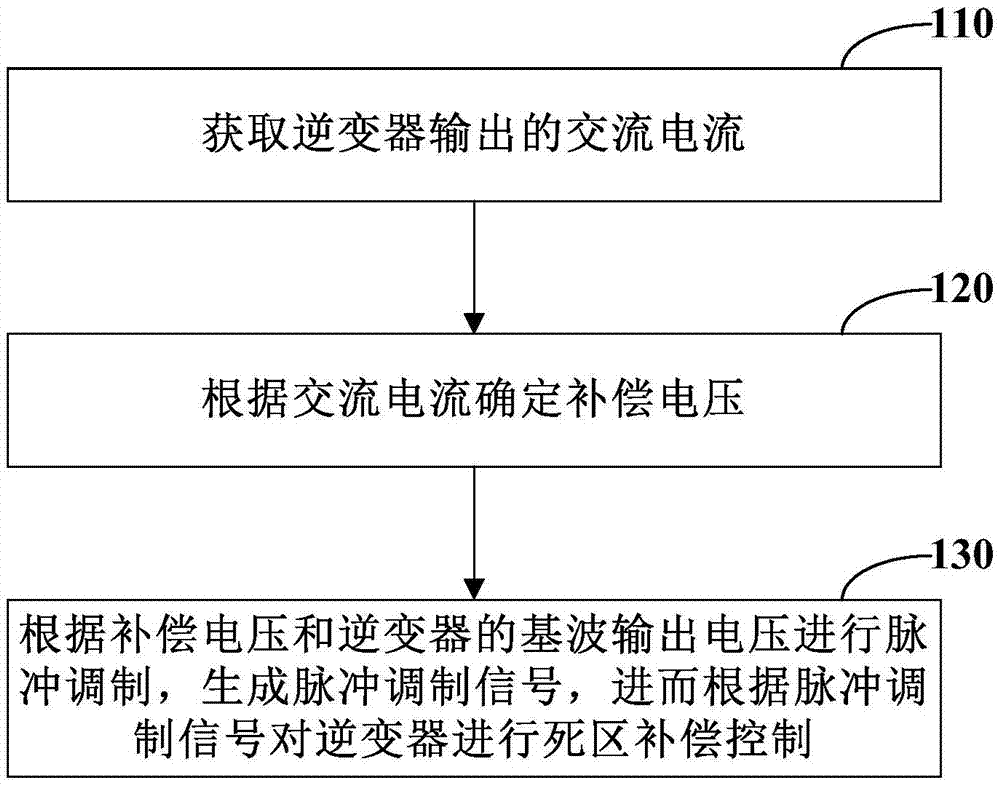
[0017] figure 1 It is a schematic flow chart of the dead zone compensation method of the inverter according to Embodiment 1 of the present invention, as shown in figure 1 As shown, the method can be performed on a controller such as an inverter, and the dead zone compensation method of the inverter includes:

[0018] Step 110: Obtain the AC current output by the inverter.

[0019] In practical applications, the three-phase current sensor can be set at the output position of the inverter to collect the AC current output by the inverter, and then transmit the collected AC current to the controller of the inverter. Thus, the inverter The controller of the inverter can obtain the AC current output by the inverter.

[0020] Step 120: Determine the compensation voltage according to the AC current.

[0021] According to an exemplary embodiment of the present invention, step 120 may include: performing 3 / 2 transformation on the AC current to obtain a current component in a synchron...

Embodiment 2

[0054] Figure 7 It is a structural schematic diagram of the dead zone compensation device of the inverter according to the second embodiment of the present invention. It can be used to execute the steps of the dead zone compensation method of the inverter according to Embodiment 1 of the present invention.

[0055] refer to Figure 7 , the dead zone compensation device of the inverter includes a current acquisition module 710 , a compensation voltage determination module 720 , a signal generation module 730 and a compensation processing module 740 .

[0056] The current obtaining module 710 is used to obtain the AC current output by the inverter.

[0057] The compensation voltage determination module 720 is used to determine the compensation voltage according to the AC current.

[0058] The signal generating module 730 is configured to perform pulse modulation according to the compensation voltage and the fundamental wave output voltage of the inverter to generate a pulse ...


PUM


Abstract

The embodiment of the invention provides a dead-time compensation method and device of an inverter. The dead-time compensation method of the inverter comprises the following steps of acquiring AC current output from the inverter; determining compensation voltage according to the AC current; carrying out pulse modulation and generating a pulse modulation signal according to the compensation voltage and fundamental wave output voltage of the inverter; and carrying out dead-time compensation control on the inverter according to the pulse modulation signal. Through the dead-time compensation method and device of the inverter, provided by the invention, the dead-time voltage is accurately and dynamically compensated, the distortion probability of the output current of the inverter is reduced, and the electric energy quality is enhanced.

Description

technical field [0001] The invention relates to the technical field of wind power, in particular to a dead zone compensation method and device for an inverter. Background technique [0002] Voltage pulse width modulation type inverters are widely used in various control occasions. In order to prevent the two power devices on the same bridge arm of the inverter from passing through and destroying the inverter, it is necessary to artificially add a dead time to the control signal. Both power devices are cut off within the time zone. In addition, when the inverter is operating, there is a delay in the switching time, and the turn-off time is often delayed, which leads to a difference between the actual voltage value and the theoretical value. These effects are called dead time. The cumulative effect of the dead zone will eventually lead to phase voltage and phase current distortion, zero current clamping effect, and torque and speed ripple, degrading system performance. [00...

Claims


Application Information

Patent Timeline
Patent Type & Authority Applications(China)
IPC IPC(8): H02M7/48H02M1/12
CPCH02M1/12H02M7/48H02M1/0016
Inventor 陈守川刘炳张国驹
Owner BEIJING ETECHWIN ELECTRIC
Learn More