A mode reconfigurable s-band transceiver radio frequency component

A technology of radio frequency components and frequency bands, applied in the field of mode-reconfigurable S-band transceiver radio frequency components, can solve the problems of no switching capability, large amount of back-end equipment, slow tracking speed, etc., to avoid signal interference and improve space Utilization, the effect of avoiding channel differentiation

Active Publication Date: 2018-06-12
NO 54 INST OF CHINA ELECTRONICS SCI & TECH GRP
View PDF6 Cites 0 Cited by
  • Summary
  • Abstract
  • Description
  • Claims
  • Application Information

AI Technical Summary

Problems solved by technology

This method can switch between different antennas according to the different signal forms on the satellite, that is, different antennas correspond to different resources on the satellite, which can ensure that the antennas work at the same time, but when the number of antennas is large, it is inevitable that the antennas will be bulky and There are big disadvantages in terms of large amount of back-end equipment and slow tracking speed, and cannot well adapt to the needs of high-mobility platforms
[0004] 2. A mechanical mode switching device is installed in a pair of antennas. This type of mode switching device is mostly used in the feed source design of reflector antennas. Although the mode switching method of this type of system has the advantage of relatively low cost, it is in the field of satellite communications. , its size is still large, the mode switching response time is slow and other shortcomings
[0005] 3. The traditional single-mode active phased array antenna has the advantages of fast beam tracking and advanced system, but it does not have the ability to switch, and users cannot switch between inter-satellite links as needed, which makes them lose Ability to reuse functions

Method used


Image

  • A mode reconfigurable s-band transceiver radio frequency component
  • A mode reconfigurable s-band transceiver radio frequency component
  • A mode reconfigurable s-band transceiver radio frequency component

Examples


Embodiment Construction

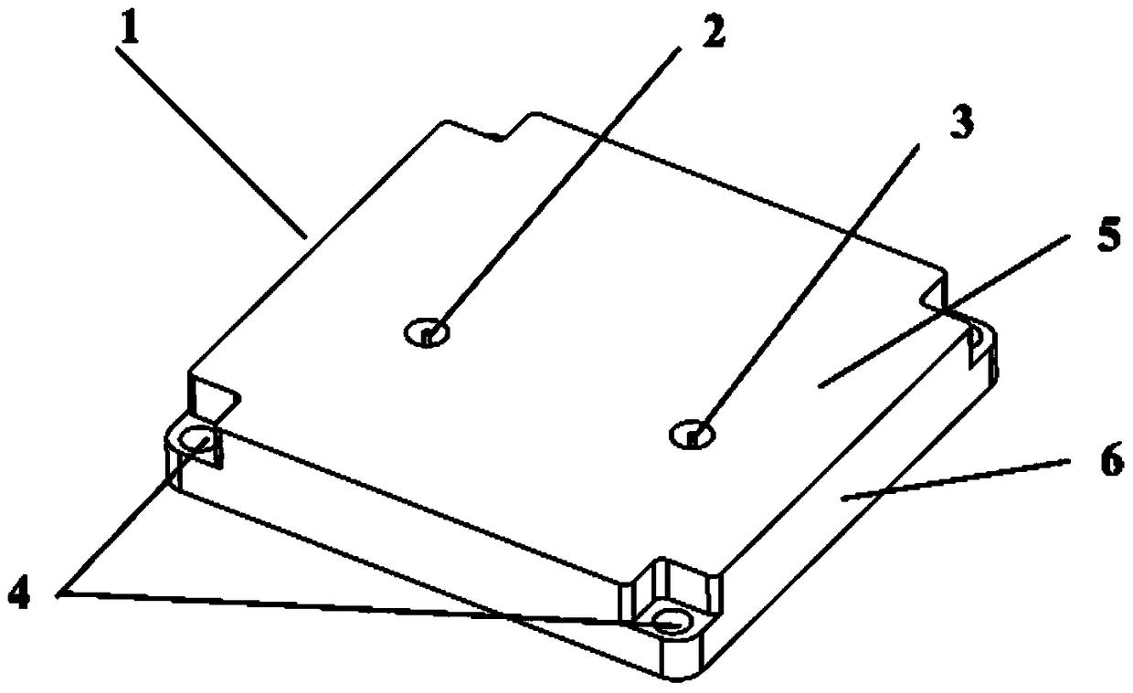
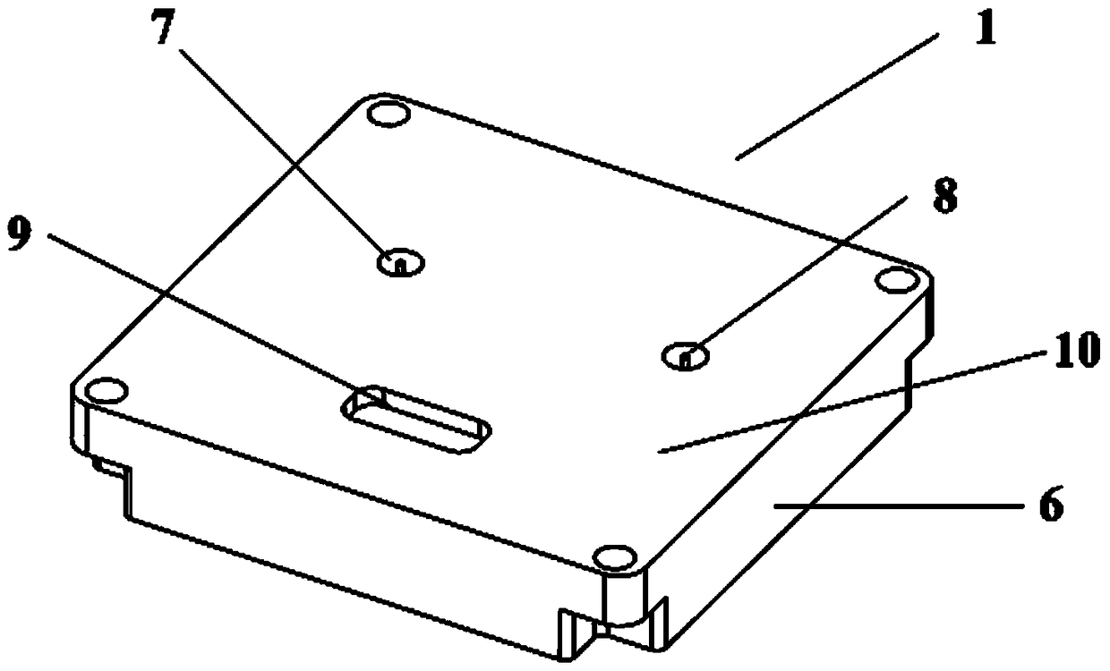
[0025] Below, combine Figure 1-Figure 3 The present invention will be further described.

[0026] In a mode reconfigurable S-band transceiver radio frequency component 1, such as figure 1 with figure 2 As shown, 1, including left-handed circular polarization signal interface 2, right-handed circular polarization signal interface 3, threaded holes for installation and fixing 4, upper cover plate 5, component cavity 6, receiving signal arranged in sequence from top to bottom Output port 7, transmission signal input port 8, control and power supply interface 9, lower cover plate 10, etc.

[0027] In a mode reconfigurable S-band transceiver radio frequency component 1, the left-handed circular polarization signal interface 2 and the right-handed circular polarization signal interface 3 are selectively connected according to the polarization form of the antenna unit connected to the front end of the radio frequency component, and the connection method is as follows SMP fast in...


PUM


Abstract

The invention relates to a mode-reconfigurable S-band transceiver radio frequency component in the field of satellite communication, including a component cavity, a left-handed circular polarization signal interface, a right-handed circular polarization signal interface, a receiving signal output port, a transmitting signal input port and a radio frequency circuit, the radio frequency circuit is connected to external equipment through a left-handed circular polarization signal interface and a right-handed circular polarization signal interface, a receiving signal output port, and a transmitting signal input port. The invention switches between channels for the transceiver components used in the active phased array antenna, thereby completing time-sharing communication between different satellites. The invention can assist the antenna system to realize functions such as fast signal tracking, signal switching, signal capture, signal sending and receiving separation and the like in fixed station, mobile station and portable station antennas.

Description

technical field [0001] The technical field involved in the present invention covers the transceiver module required by the active phased array antenna in the electronic information system, which can be widely used in the fields of satellite communication, satellite navigation, satellite positioning, remote control and telemetry, etc., specifically a Mode reconfigurable S-band transceiver RF components. The invention is also particularly suitable for satellite communication, switching between channels for the transceiver components used in the active phased array antenna, so as to complete time-sharing communication between different satellites. The invention can assist the antenna system to realize functions such as fast signal tracking, signal switching, signal capture, signal sending and receiving separation and the like in fixed station, mobile station and portable station antennas. Background technique [0002] In the field of satellite communications, with the continuo...

Claims


Application Information

Patent Timeline
Patent Type & Authority Patents(China)
IPC IPC(8): H04B1/40H04B7/185
CPCH04B1/40
Inventor 韩国栋王焕菊高冲张宙肖松卢炜
Owner NO 54 INST OF CHINA ELECTRONICS SCI & TECH GRP
Why Eureka
Try Eureka