Fault diagnosis analysis method, fault diagnosis device, fault analysis device and fault diagnosis analysis system

A fault diagnosis device and fault diagnosis technology, applied in transmission monitoring/testing/fault measurement systems, etc., can solve problems such as incompleteness and difficulty in reproduction, and achieve the effect of simple and convenient operation and maintenance

Inactive Publication Date: 2016-03-30
ZTE CORP
View PDF3 Cites 8 Cited by
  • Summary
  • Abstract
  • Description
  • Claims
  • Application Information

AI Technical Summary

Problems solved by technology

[0004] In addition, in the process of equipment operation and maintenance, when the equipment fails, the common way for the staff to solve it is to reproduce it in the laboratory according to the description of the staff, and determine the solution according to the reproducti

Method used


Image

  • Fault diagnosis analysis method, fault diagnosis device, fault analysis device and fault diagnosis analysis system
  • Fault diagnosis analysis method, fault diagnosis device, fault analysis device and fault diagnosis analysis system
  • Fault diagnosis analysis method, fault diagnosis device, fault analysis device and fault diagnosis analysis system

Examples


Embodiment Construction

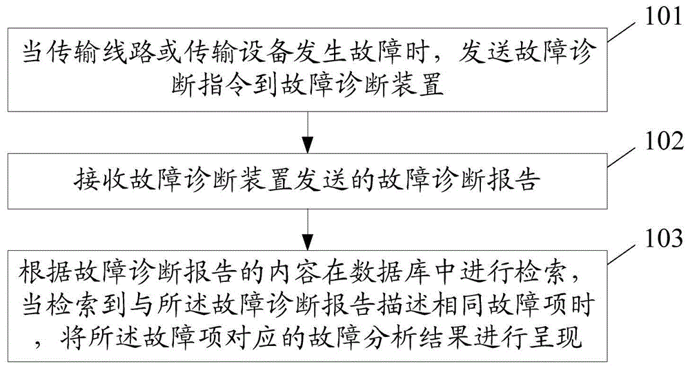
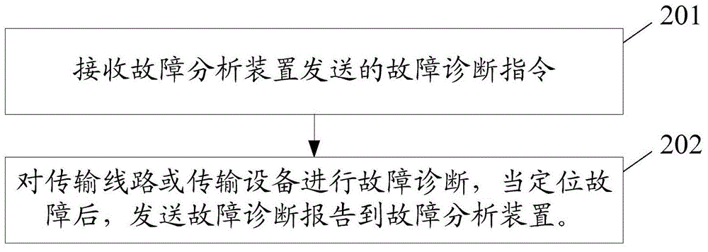
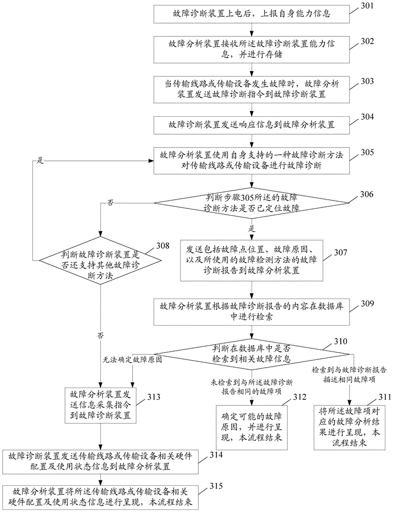
[0059] In the embodiment of the present invention, when a failure occurs on the transmission line or transmission equipment, the fault analysis device sends a fault diagnosis instruction to the fault diagnosis device; Diagnose, after locating the fault, send the fault diagnosis report to the fault analysis device; the fault analysis device receives the fault diagnosis report sent by the fault diagnosis device, and searches in the database according to the content of the fault diagnosis report. When the report describes the same fault item, the fault analysis result corresponding to the fault item in the database is presented.

[0060] When the same fault item as that in the fault diagnosis report is not retrieved, the method further includes: determining the possible The cause of the failure, and present the determined possible cause of the failure and the corresponding solution to the failure.

[0061] And when the fault cannot be located, or the fault item corresponding to ...


PUM


Abstract

The present invention provides a fault diagnosis analysis method. The fault diagnosis analysis method comprises: when a failure happens on a transmission line or a transmission device, a fault diagnosis instruction is sent to a fault diagnosis device; a fault diagnosis report sent by the fault diagnosis device is received; the retrieval is performed in a database according to the content of the fault diagnosis report, and fault analysis results corresponding to fault items in the database are displayed when the retrieved fault items are the same as the description of the fault diagnosis report. The present invention further provides another fault detection analysis method, a fault diagnosis device, a fault analysis device and a fault diagnosis analysis system.

Description

technical field [0001] The invention relates to optical transmission equipment maintenance technology, in particular to a method, device and system for fault diagnosis of optical transmission lines or transmission equipment. Background technique [0002] With the continuous development of optical communication, optical transmission equipment continues to be used more and more widely, and more and more business types are involved. The complexity of optical transmission equipment and transmission lines has resulted in the operation and maintenance of equipment. The technical requirements are constantly increasing. [0003] In the current operation and maintenance, the common practice is that during project commissioning, R&D personnel travel to various project sites to support project commissioning and solve various problems in the project, which undoubtedly increases labor costs. When there are many engineering locations opened at the same time, R&D support personnel even ne...

Claims


Application Information

Patent Timeline
IPC IPC(8): H04B10/07
CPCH04B10/07
Inventor 武春秀
Owner ZTE CORP
Why Eureka
Try Eureka