Optical fiber monitoring system

A monitoring system and optical cable technology, which is applied in the field of optical cable monitoring systems, can solve the problems of long maintenance time for damage to optical cable communication systems and the inability to monitor actively in real time, and achieve the effects of shortening maintenance time, reducing pressure, and improving reliability

Inactive Publication Date: 2016-03-30
GUILIN TRYIN TECH CO LTD
View PDF4 Cites 4 Cited by
  • Summary
  • Abstract
  • Description
  • Claims
  • Application Information

AI Technical Summary

Problems solved by technology

[0004] The invention provides an optical cable monitoring system, which solves the problems that the existing optical

Method used


Image

  • Optical fiber monitoring system

Examples


Embodiment Construction

[0014] The present invention will be further described below in conjunction with embodiment.

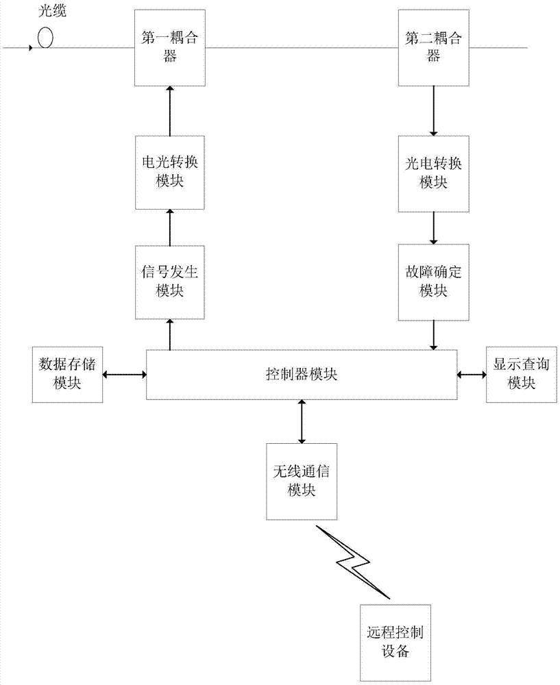
[0015] A fiber optic cable monitoring system, such as figure 1 As shown, it includes optical cable, first coupler, electro-optical conversion module, signal generation module, data storage module, controller module, display query module, fault determination module, photoelectric conversion module, second coupler, wireless communication module and remote control equipment;

[0016] The optical cable is connected to the second coupler through the first coupler; the output end of the second coupler is connected to the input end of the controller module through the photoelectric conversion module and the fault determination module; the display query module and the data storage module connected with the controller module; the output end of the controller module is connected with the input end of the first coupler through the signal generation module and the electro-optical conversion mod...


PUM


Abstract

The invention provides an optical fiber monitoring system, and belongs to the field of optical fiber communication. The optical fiber monitoring system comprises an optical fiber, a first coupler, an electro-optical conversion module, a signal generation module, a data storage module, a controller module, a display query module, a fault determination module, a photoelectric conversion module, a second coupler, a wireless communication module and a remote control device. According to the optical fiber monitoring system, the optical fiber in an area is monitored by using the controller module in a centralized controlling and processing manner, hidden dangers can be found in time, and thereby passive maintenance becomes active maintenance, the maintenance time is shortened, the pressure of maintenance personnel is relived, and the operating reliability of the optical fiber is improved; by using the remote control device, a user can remotely monitor the performance of the optical fiber in real time, thus the remote real-time monitoring effect is acheived; and the problem that the existing optical fiber communication system is long in maintenance time after damage and cannot actively monitor in real time is solved.

Description

technical field [0001] The invention relates to a monitoring system for optical cable communication, in particular to an optical cable monitoring system. Background technique [0002] With the development of the information society, the optical cable network continues to expand, and the optical cable information transmission has become an indispensable information transmission channel for information sharing in today's society. However, due to some human or non-human factors, the frequent interruption of the optical cable will directly cause the interruption of the optical cable communication system running on this optical cable, which will adversely affect the communication operation, bring huge economic losses to people, and also give people information. Sharing is inconvenient. [0003] Because the optical cable network system covers a wide area, the network routing is complex, the overhead and buried pipelines are laid alternately, and there are many nodes; therefore, a...

Claims


Application Information

Patent Timeline
IPC IPC(8): H04B10/077
CPCH04B10/0771
Inventor 姚峰
Owner GUILIN TRYIN TECH CO LTD
Why Eureka
Try Eureka