
Vehicle air-conditioning device

A technology for air conditioning devices and vehicles, which is applied in household refrigeration devices, vehicle components, applications, etc., and can solve problems such as short working hours

Inactive Publication Date: 2016-03-30
JAPAN CLIMATE SYSTEMS CORP +1
View PDF4 Cites 4 Cited by
  • Summary
  • Abstract
  • Description
  • Claims
  • Application Information

AI Technical Summary

Problems solved by technology

However, in recent years, electric vehicles without an internal combustion engine, plug-in hybrid vehicles with an internal combustion engine that operates for a short period of time, etc. have become popular

Method used


Image

  • Vehicle air-conditioning device
  • Vehicle air-conditioning device
  • Vehicle air-conditioning device

Examples


Embodiment Construction

[0101] Hereinafter, embodiments of the present invention will be described in detail based on the drawings. It should be noted that the following preferred embodiments are only preferred examples in nature, and are not intended to limit the present invention, the application object of the present invention or the use of the present invention.

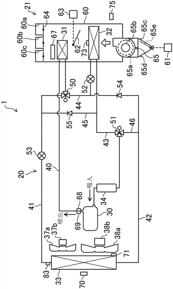
[0102] figure 1 It is a schematic configuration diagram of the vehicle air conditioner 1 according to the embodiment of the present invention. The vehicle in which the vehicle air conditioner 1 is mounted is an electric vehicle including a running battery (not shown) and a running electric motor (not shown).

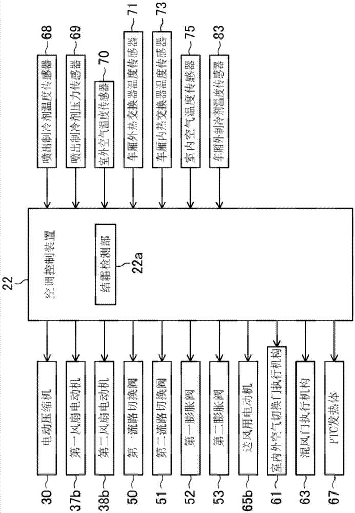
[0103] The air conditioner 1 for a vehicle includes a heat pump device 20, an air conditioner unit 21 in the vehicle compartment, and an air conditioner control device 22 (in the figure 2 shown in ).

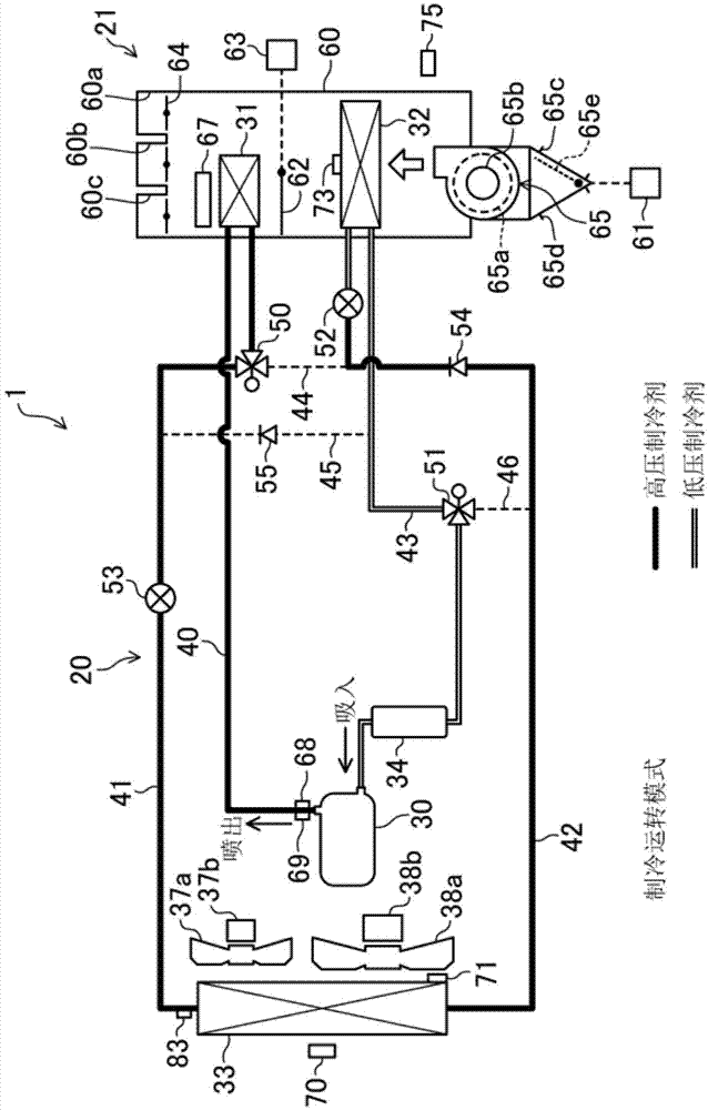
[0104] The heat pump device 20 includes: an electric compressor 30 for compressing refrigerant; a downstream indoor heat excha...


PUM


Abstract

When the operation mode of a heat pump device (20) is a first heating operation mode that uses two in-cabin heat exchangers (31, 32), in the case that a cabin exterior heat exchanger (33) has been detected to have frost, a second heating operation mode that uses one in-cabin heat exchanger (31) is switched to, and then a defrosting operation mode is switched to.

Description

technical field [0001] The present invention relates to a vehicle air conditioner mounted on a vehicle, and more particularly to a vehicle air conditioner including a heat pump device. Background technique [0002] Conventionally, waste heat of an internal combustion engine has been used as a heating heat source of an air conditioner for a vehicle. In recent years, however, electric vehicles not equipped with an internal combustion engine, plug-in hybrid vehicles equipped with an internal combustion engine but whose operation time is short, and the like have become popular. Therefore, how to achieve comfortable air conditioning on these vehicles becomes a problem. [0003] Patent Document 1 discloses a heat pump device including an electric compressor as a vehicle air conditioner. In addition to the electric compressor, this heat pump device is equipped with an exterior heat exchanger installed outside the cabin, an expansion valve, an upstream interior heat exchanger, and...

Claims


Application Information

Patent Timeline
IPC IPC(8): B60H1/22
CPCB60H1/00921F25B6/04F25B47/022F25B2347/02F25B5/04F25B2347/023F25B2400/0409F25B2400/0411B60H2001/00961F25B41/39F25B41/20F25B2313/02322B60H1/321B60H1/00785B60H1/00328F25B13/00F25D21/004F25D21/02F25D21/125
Inventor 滨本浩深渡瀬康平大竹庆彦小森晃松元昂宫村宪浩
Owner JAPAN CLIMATE SYSTEMS CORP
Learn More