
Harvester provided with drainage tank

A technology for drainage tanks and harvesters, which is applied to harvesters, agricultural machinery and implements, and other applications. It can solve the problems of electromagnetic switch coil burnout, parts corrosion, and engine life reduction, so as to prolong the service life and reduce labor intensity. , the effect of increasing the driving speed

Inactive Publication Date: 2016-04-06
CHONGQING SHINERAY AGRI MACHINERY
View PDF8 Cites 3 Cited by
  • Summary
  • Abstract
  • Description
  • Claims
  • Application Information

AI Technical Summary

Problems solved by technology

[0002] In agricultural production, the harvester is used to harvest crops; if it is working in the field, frequent turns or U-turns will occur. If the turn is too early or too slow, the harvester may not be able to harvest the corresponding crops. You should first accurately judge the machine The position of the head is at the angle that can just turn around the harvested field. At this time, it will be reminded in time and quickly rotate to the required direction. However, the existing method is judged by the driver, which requires certain experience and skills, and it is also necessary to There may be some security risks
[0003] If rainwater flows into the engine, it will affect the performance of the engine. If rainwater enters the switch, some parts will be rusted and cannot work normally, or the electromagnetic switch coil will be burned directly.
If the water is collected in winter, it will freeze to ice, so that the moving iron core and shift fork will be frozen, so that the engine cannot be started normally, and the life of the engine will be greatly reduced.

Method used


Image

  • Harvester provided with drainage tank
  • Harvester provided with drainage tank

Examples


Embodiment Construction

[0029] The present invention will be further described below in conjunction with drawings and embodiments.

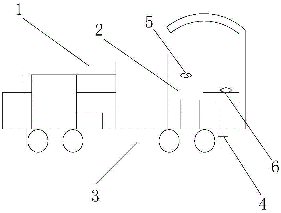
[0030] As shown in the figure, a harvester provided with a drainage tank provided in this embodiment includes a working room 1, a cab, a walking device 3, a distance detector 4, a turning indicator 5 and a controller 6;

[0031] The working room includes a working room main body 2, a threshing bin, a storage bin, a material inlet and a material outlet; The bin is located in the main body of the working room, the threshing bin and the storage bin are connected by a conveyor belt, and the walking device is set on both sides of the main body of the working room;

[0032] The cab includes a cab main body, a console, a steering wheel, an engine and a driver's seat. The console is arranged at the left end of the cab main body, the steering wheel is arranged on the console, the engine is arranged at the bottom of the console, and the driver's seat is arranged at the right end ...


PUM


Abstract

The invention discloses a harvester provided with a drainage tank. The harvester comprises an operating room, a cab, a running device, a distance detector, a turning reminder and a controller. The distance detector is arranged on the running device. The turning reminder is arranged on the main body of the cab. The drainage tank and a motor are arranged in the cab. The motor comprises a box body and a waterproof cover. The controller is arranged on a control desk. An infrared receiving device inputs received laser signals to the controller so as to obtain the distance between the harvester and a front barrier. The turning reminder receives turning control signals and emits turning reminding signals. The harvester employs the fast and sharp turning reminder, so that the harvester can detects that whether a fast and sharp turning is needed at a headland according to the terrain of a field. The harvester can accurately determine the head position where the harvester can just turn the headland, then the harvester can timely remind a driver of turning at the moment, and the harvester can rapidly rotate to the required direction, so that the running speed of the harvester is improved, and the labor intensity of the driver is reduced.

Description

technical field [0001] The invention relates to the field of agricultural machinery and equipment, in particular to a harvester provided with drainage grooves. Background technique [0002] In agricultural production, the harvester is used to harvest crops; if it is working in the field, frequent turns or U-turns will occur. If the turn is too early or too slow, the harvester may not be able to harvest the corresponding crops. You should first accurately judge the machine The position of the head is at the angle that can just turn around the harvested field. At this time, it will be reminded in time and quickly rotate to the required direction. However, the existing method is judged by the driver, which requires certain experience and skills, and it is also necessary to There may be certain security risks. [0003] If rainwater flows into the engine, it will affect the working performance of the engine. If rainwater enters the switch, some parts will be rusted and unable to...

Claims


Application Information

Patent Timeline
Patent Type & Authority Applications(China)
IPC IPC(8): A01D75/00
CPCA01D75/00
Inventor 汪仁凡李川费长雷
Owner CHONGQING SHINERAY AGRI MACHINERY
Learn More