Haemorrhoids loop ligature device

A technology for ligation and hemorrhoids, applied in surgical cutting instruments, medical science, surgery, etc., can solve the problems that the suction effect is not as good as that of electric suction ligation, does not display negative pressure value, and is inconvenient to use, etc., and achieves a simple and reliable structure , unique concept, easy to disassemble effect

Inactive Publication Date: 2016-04-06
朱俊余
7 Cites 6 Cited by

AI-Extracted Technical Summary

Problems solved by technology

Suction ligation devices can be divided into two types: electric suction ligation devices and manual suction ligation devices. The former has strong suction and sufficient suction due to the negative pressure generated by the negative pressure pump, but its disadvantage requires a heavy load. Pressure pump, not only high equipment cost, but ...

Abstract

The invention discloses a haemorrhoids loop ligature device. The haemorrhoids loop ligature device comprises a main system, a loop ligature operation system and a vacuum aspiration operation system. The three systems are ingeniously combined to form the haemorrhoids loop ligature device, negative pressure meeting clinical needs can be generated without a negative pressure pump, the negative pressure value can be displayed, more functions are realized, and using is more convenient.

Application Domain

Technology Topic

Orthodontic ligatureHemorrhoids +2

Image

  • Haemorrhoids loop ligature device
  • Haemorrhoids loop ligature device
  • Haemorrhoids loop ligature device

Examples

  • Experimental program(1)

Example Embodiment

[0020] In order to illustrate the present invention in detail, the present invention will be further described in detail below with reference to the accompanying drawings and specific implementation examples.
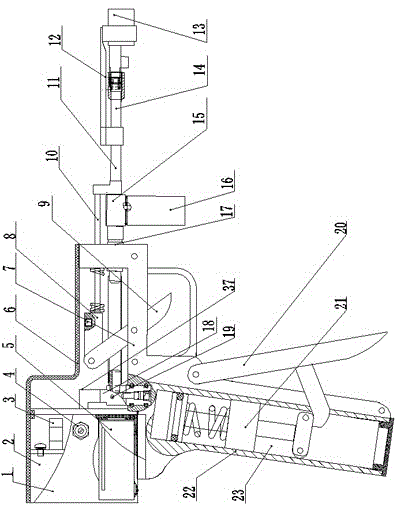
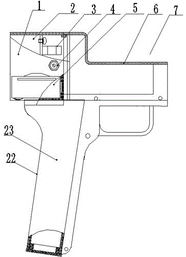
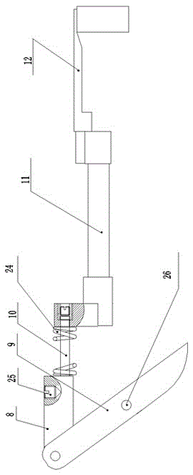
[0021] from Figure 1-Figure 7 As can be seen from the above, the present invention includes a main body system, a ligation operating system, and a negative pressure suction operating system. The main body system includes a ligation device body 7, an upper cover 6, and a pressure display device 1. There is a handle 22, an air chamber 23 is arranged in the handle 22, the pressure display device 1 is arranged above the handle 22, and the pressure display device 1 is provided with a battery box 5, a pressure sensor 2, an external power socket 4 and a switch 3, the upper cover 6 is arranged on the upper part of the main body 7 of the ligation device; the described ligation operating system includes a push block 8, a trigger 9, an ejector rod 10, a push rod 11, and a ligation push ring 12, and the rear end of the ligation push ring 12 is inserted into the The front end of the push rod 11, the rear end of the push rod 11 is connected with the front end of the push rod 10, a return spring 24 is provided on the push rod 10, the rear end of the push rod 10 is connected with the push block 8, and the other side of the push block 8 is connected. One end is connected with the trigger 9, and the trigger 9 provides power for the ligation operation; the negative pressure suction operating system includes a suction cup 13, a suction rod 14, a connecting body 15, a pollution interception bottle 16, a screw 17, a one-way valve 18, an injection The oil pipe 19, the suction rod 20 and the piston device 21. The suction cup 13 includes a suction cup body 33 and a suction cup handle 29. A puncture needle hole 28 is provided at the bottom of the suction cup body 33 and is closed with a rubber sheet. On the puncture hole 28, the suction cup handle 29 is provided with a puncture needle fixing bracket 30 for fixing the needle handle of the puncture needle. One end of the suction rod 14 is connected with the suction cup handle 29 through the connecting sleeve 34, and the other end is connected with the front end of the connecting body 15. The rear end of the connecting body 15 is connected with the screw 17, and the lower end of the connecting body 15 is connected with the sewage interception bottle 16. There are two holes below the connecting body 15, and the front hole 26 is equipped with a thin tube 35 for To prevent dirt from contaminating the connecting body and the flushing suction rod, the rear hole 27 is an exhaust passage, and the side of the connecting body 15 is provided with an exhaust hole 51. The one-way valve 18 is connected to the one-way valve 18 through the pipe 36. The upper part of the one-way valve 18 is connected to the pressure sensor 2 through the L-shaped pipe 37. There is a screw hole I38, the screw hole I38 is connected with the rear end of the oil injection pipe 19, the front end of the oil injection pipe 19 is fixed to the front end of the ligator main body 7, the upper end of the suction rod 20 is connected with the ligation device main body 7, and the middle part is The connecting piece 31 is connected with the slider 39 of the piston device 21. The suction rod 20 provides power for generating negative pressure. The piston device 21 is placed in the air chamber 23 of the ligation device main body 7. The piston device 21 contains a piston 42 and a sealant. Ring 43 , return spring 32 , air chamber rear block 40 , slider 39 , pulley 41 .
[0022] The front part of the oil injection pipe 19 is fixed to the front end of the ligator main body 7 by the nut 46 and the screw I44. On the side screw hole I38 of the valve 18, the screw I44 and the connecting screw 45 are connected by a pipe 47.
[0023] The trigger 9 is provided with a screw hole II 26, and the trigger 9 is fixed on the main body 7 of the ligation device with screws.
[0024] Negative pressure suction system such as Figure 4 , Figure 5 , Image 6 , Figure 7 As shown, the suction cup 13 is disposable, made of polypropylene non-toxic plastic, and has an injection function. The bottom of the suction cup 13 is provided with a puncture hole 28 with a diameter of 3 mm and is closed with a rubber sheet. The suction cup handle 29 is provided with a bracket 30 to fix the handle of the puncture needle. When working, the puncture needle is a puncture needle of a No. 5 infusion set. The suction rod 14 plays the role of connection and support. The front end is connected to the suction cup 13 through the connecting sleeve 34, and the rear end is connected to the connecting body 15. The rear end of the connecting body 15 is connected to the screw rod 17. The thin tube 35 of the connecting body 35, the rear hole 27 is an exhaust passage, the side of the connecting body 15 is provided with an exhaust hole 51, the outer opening of the exhaust hole 51 is blocked with screws III50, and the interception bottle 16 is made of polypropylene plastic injection molding, Connected below the connecting body 15 , the screw 17 is connected to the connecting body 15 at the front, and the rear end is connected to the one-way valve 18 through a medical plastic tube 36 . The one-way valve acts as a one-way seal to maintain the suction negative pressure. The upper part is connected to the pressure sensor 2 through the L-shaped tube 37, and the lower end is fixed above the air chamber 23 in the handle 22 of the ligation device main body 7. There is a screw hole I38, and the screw hole I38 is connected with the oil filling pipe 19. The front end of the oil injection pipe 19 is fixed to the front end of the ligation device main body 7, the upper end of the suction rod 20 is connected to the ligation device main body 7, and the middle part is connected to the slider 39 in the piston device 21 through the connecting piece 31, and the piston device 21 is placed in the sleeve. inside the air chamber 23 of the tying device main body 7 .
[0025] image 3 , the size of the collar 12 should be matched with the suction cup 13, its rear end is inserted into the front end of the push rod 11, the push rod 11 is sleeved on the outside of the ejector rod 10, the front end of the ejector rod 10 is connected to the push rod 11, and the rear end is used for The screw 25 is fixed on the push block 8 with a return spring 24 therebetween. The trigger 9 is provided with a screw hole II 26, and the trigger 9 is fixed on the ligation device main body 7 with screws. The upper part of the trigger 9 is connected with the push block 8 to provide power for the ligation operation.
[0026] The pressure sensor of the present invention adopts DP101 type, the battery adopts 15V laminated battery, and the external power supply adopts 12-24V direct power supply. The combination of the main body 7 of the ligation device, the upper cover 6 and the pressure display device 1 adopts a button-type combination, which is convenient to disassemble.
[0027] The puncture needle was a No. 5 infusion set puncture needle purchased directly in the market.

PUM

no PUM

Description & Claims & Application Information

We can also present the details of the Description, Claims and Application information to help users get a comprehensive understanding of the technical details of the patent, such as background art, summary of invention, brief description of drawings, description of embodiments, and other original content. On the other hand, users can also determine the specific scope of protection of the technology through the list of claims; as well as understand the changes in the life cycle of the technology with the presentation of the patent timeline. Login to view more.

Similar technology patents

Wear edge assembly

InactiveUS20050229442A1Effective wearEasy to disassembleSoil-shifting machines/dredgersEngineeringIncreased risk
Owner:ESCO CORP

Classification and recommendation of technical efficacy words

  • Easy to disassemble
  • Avoid cross infection

Disposable endoscope sheath

Owner:TIANJIN BOLANG SCI TECH DEV
Why Eureka
Try Eureka