Eureka AIR delivers breakthrough ideas for toughest innovation challenges, trusted by R&D personnel around the world.

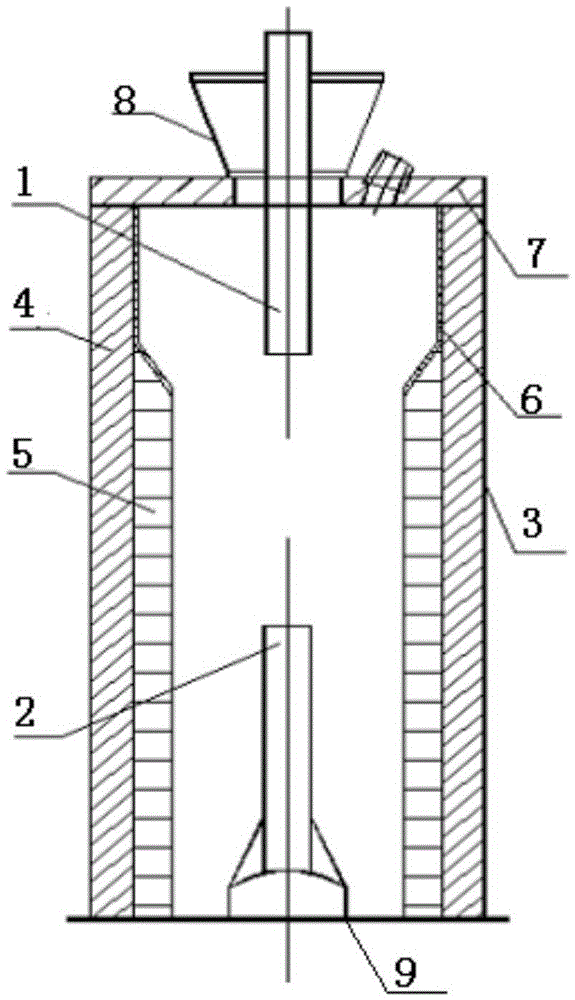
Graphitizing furnace liner structure

A graphitization furnace and lining technology, applied in the field of furnace lining structure, to achieve the effect of ensuring long-term stable operation, good corrosion resistance and erosion resistance, and no impact on product quality

Inactive Publication Date: 2016-04-06
CHNA ENERGY INVESTMENT CORP LTD +1
View PDF8 Cites 0 Cited by
  • Summary
  • Abstract
  • Description
  • Claims
  • Application Information

AI Technical Summary

Problems solved by technology

This structure can ensure that the heat-resistant temperature of the furnace body reaches above 2500°C, solves the coking phenomenon caused by the accumulation of materials and cannot flow, and ensures the long-term normal operation of the equipment

Method used


Image

  • Graphitizing furnace liner structure

Examples


Embodiment 1

[0034] The total height of the furnace body of the electric calciner is 7900 mm, and its outer diameter is 3000 mm, including the inner lining structure of the graphitization furnace. The structure includes a furnace shell 3 , an external lining 4 and a carbon brick lining 5 in sequence from outside to inside. The furnace shell 3 adopts steel structure to make a cylindrical type, and the thickness of the furnace shell 3 is 8mm; the outer lining 4 is made of high alumina bricks, aluminum silicate plates, and clay bricks from the inside to the outside, and the high alumina brick layer is The thickness of the aluminum silicate plate layer is 15-20mm, and the thickness of the clay brick layer is 230mm; The slope section of the lining 4 transition, the top of the slope section is located at a distance of 6m from the bottom of the furnace, the vertical height of the slope section is 600mm, and the vertical height of the slope section accounts for 6 / 79 of the height of the entire fur...

Embodiment 2

[0042]The total height of the furnace body of the electric calciner is 7900 mm, and its outer diameter is 3000 mm, including the inner lining structure of the graphitization furnace. The structure includes a furnace shell 3, an external lining 4 and a carbon brick lining 5 from outside to inside. The furnace shell 3 is made of cylindrical steel structure, and the thickness of the furnace shell 3 is 8mm; the outer lining 4 is made of high alumina bricks, aluminum silicate plates, and clay bricks from the inside to the outside, and the high alumina brick layer is The thickness of the aluminum silicate plate layer is 15-20mm, and the thickness of the clay brick layer is 230mm; The slope section of the lining 4 transition, the top of the slope section is located at a distance of 6m from the bottom of the furnace, the vertical height of the slope section is 400mm, and the vertical height of the slope section accounts for 4 / 79 of the height of the entire furnace body. The slope surf...


PUM

PropertyMeasurementUnit
Thicknessaaaaaaaaaa
Thicknessaaaaaaaaaa
Vertical heightaaaaaaaaaa

Abstract

The invention relates to a graphitizing furnace liner structure. From outside to inside, the structure sequentially comprises a furnace shell (3), an external liner (4) constructed by a refractory material layer by layer and a carbon brick liner (5), wherein the top of the carbon brick liner (5) is provided with a slope section which gradually transits to the external liner (4); the top of the slope section is about 5.9-6.9m away from the furnace bottom; and the vertical height of the slope section accounts for about 4 / 79-6 / 7 of the height of the whole furnace body. The structure ensures no accumulation of the material, and has favorable flowability. The slope section and one side of the preheating zone towards the inside of the furnace body are respectively coated with an anti-coking paint layer to prevent the preheating zone from coking. No carbon brick is constructed on the section 1000-1500mm below the furnace cover, thereby preventing the top electrode from directly discharging to the carbon bricks due to the electric conductivity increase after the carbon bricks are subjected to high temperature.

Description

technical field [0001] The invention relates to a lining structure of a furnace body, in particular, the invention relates to a lining structure of a graphitization furnace. Background technique [0002] At present, with the development of anthracite graphitization technology, the temperature required for graphitization is generally higher than 2000°C, even reaching above 2500°C. Whether the graphitization furnace can continue to operate normally at such a high temperature depends critically on the material and structure of the furnace lining. The furnace lining in the prior art generally adopts two construction methods: [0003] One is to adopt the structural form of 1350KVA electric calciner, and use refractory materials such as carbon bricks to build from the bottom of the furnace shell to the lower surface of the furnace cover, forming a cylindrical space in the furnace. The heat-resistant temperature of the furnace body is lower than 1800°C. [0004] The second is th...

Claims


Application Information

Patent Timeline
IPC IPC(8): C01B31/04
Inventor 马红梅杨忠福王晓博韩喜梅杨光明马俊斯
Owner CHNA ENERGY INVESTMENT CORP LTD
Why Eureka
Eureka Blog
Learn More