Knitting frame

A fixed frame and movable frame technology, applied in the field of woven frames, can solve the problems of inconvenient operation, weight, and large volume, and achieve the effects of convenient operation, small size, and simple adjustment methods

Active Publication Date: 2016-04-06
青海索琳手工艺术品有限公司
View PDF8 Cites 2 Cited by
  • Summary
  • Abstract
  • Description
  • Claims
  • Application Information

AI Technical Summary

Problems solved by technology

[0003] The purpose of the present invention is to provide a braiding frame

Method used


Image

  • Knitting frame
  • Knitting frame
  • Knitting frame

Examples


Embodiment 1

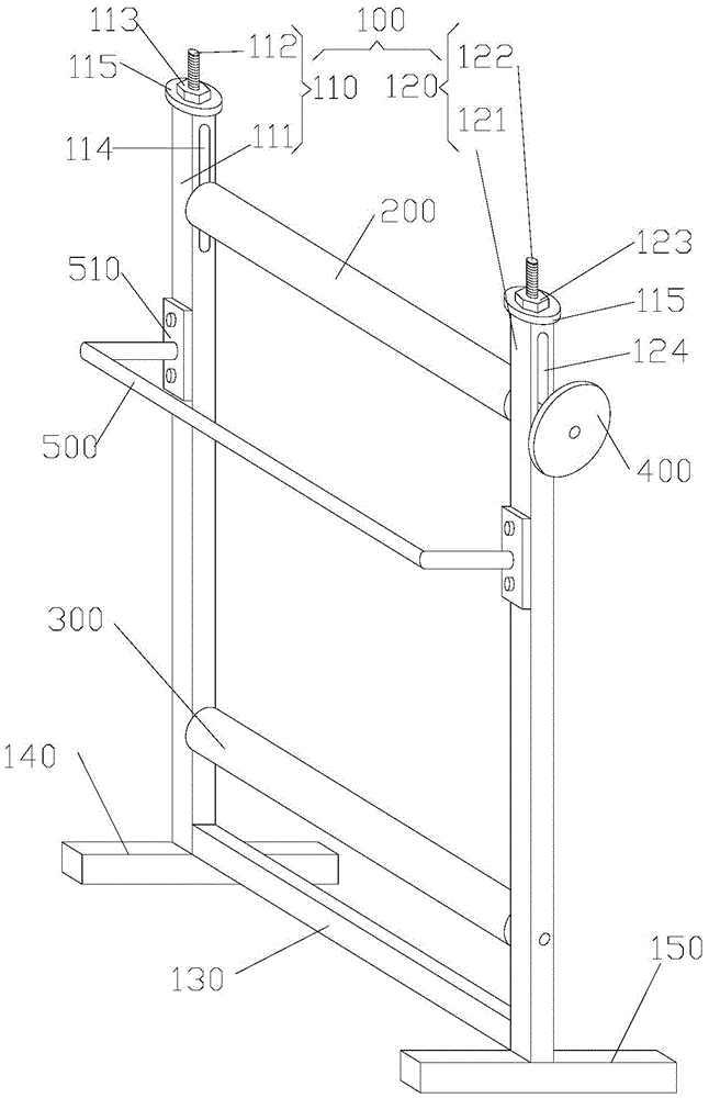
[0043] Embodiment 1, with reference to Figure 1 to Figure 6

[0044] Such as figure 1 As shown, the present embodiment provides a braiding frame, including a bracket 100, an upper roller 200 and a lower roller 300, the bracket 100 includes a left support frame 110 and a right support frame 120, and the left support frame 110 includes a first fixed frame 111 and a The first movable frame 112, the first movable frame 112 is movably connected with the first fixed frame 111, the left support frame 110 is provided with the first driver 113 that drives the first movable frame 112 to move up and down, and the right support frame 120 includes a second fixed frame. Frame 121 and the second movable frame 122, the second movable frame 122 is movably connected with the second fixed frame 121, the right support frame 120 is provided with the second driver 123 that drives the second movable frame 122 to move up and down, the lower roller 300 One end is rotatably connected with the first ...

Embodiment 2

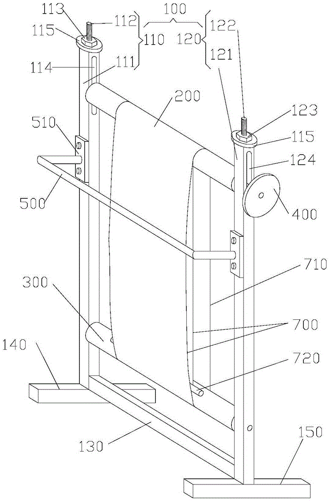
[0056] Embodiment 2, with reference to Figure 7

[0057] As shown, the present embodiment provides a braiding frame, including a bracket 100, an upper roller 200 and a lower roller 300, the bracket 100 includes a left support frame 110 and a right support frame 120, and the left support frame 110 includes a first fixed frame 111 and a The first movable frame 112, the first movable frame 112 is movably connected with the first fixed frame 111, the left support frame 110 is provided with the first driver 113 that drives the first movable frame 112 to move up and down, and the right support frame 120 includes a second fixed frame. Frame 121 and the second movable frame 122, the second movable frame 122 is movably connected with the second fixed frame 121, the right support frame 120 is provided with the second driver 123 that drives the second movable frame 122 to move up and down, the lower roller 300 One end is rotatably connected with the first fixed frame 111, and the other...


PUM


Abstract

The invention provides a knitting frame and belongs to the field of hand knitting devices. The knitting frame comprises a support, an upper rolling shaft and a lower rolling shaft, wherein the support comprises a left supporting frame and a right supporting frame. The left supporting frame comprises a first fixed rack and a first movable rack, wherein a first driving part for driving the first movable rack to move vertically is arranged on the left supporting frame. The right supporting frame comprises a second fixed rack and a second movable rack, wherein a second driving part for driving the second movable rack to move vertically is arranged on the right supporting frame. One end of the lower rolling shaft is in rotary connection with the first fixed rack, the other end of the lower rolling shaft is in rotary connection with the second fixed rack, one end of the upper rolling shaft is in rotary connection with the first movable rack, and the other end of the upper rolling shaft is in rotary connection with the second fixed rack. The knitting frame is small in size, light in weight and simple in structure, can be used for knitting multiple types of blankets and is simple in operation and convenient to use, and the distance between the upper rolling shaft and the lower rolling shaft can be changed through the first driving part and the second driving part.

Description

technical field [0001] The invention relates to the field of hand knitting devices, in particular to a knitting frame. Background technique [0002] Existing hand-knitting devices are all large-scale weaving machine beams. This weaving device has a relatively large weight and volume, and is extremely inconvenient to install, so it can only weave a large blanket type. In addition, the distance between the upper roller and the lower roller on the braiding machine beam must be changed through a matching hydraulic jack, which has a complicated structure and is very inconvenient to operate. Contents of the invention [0003] The object of the present invention is to provide a braiding frame to solve the problems of heavy weight, large volume and inconvenient operation. [0004] The present invention is achieved like this: [0005] The invention provides a braiding frame, which includes a bracket, an upper roller and a lower roller, the bracket includes a left support frame an...

Claims


Application Information

Patent Timeline
IPC IPC(8): D04C7/00
CPCD04C7/00
Inventor 杨韶鹏
Owner 青海索琳手工艺术品有限公司
Why Eureka
Try Eureka