Eureka AIR delivers breakthrough ideas for toughest innovation challenges, trusted by R&D personnel around the world.

Symmetrical semi-shading type tidal current energy generation device

A shielding device and tidal energy technology, applied in the directions of hydroelectric power generation, reaction engine, engine components, etc., can solve the problems of reducing energy harvesting efficiency and hindering the rotation of hydraulic turbines, so as to improve energy harvesting efficiency, enhance energy harvesting efficiency and electric energy output. stable effect

Active Publication Date: 2016-04-06
ZHEJIANG OCEAN UNIV
View PDF7 Cites 8 Cited by
  • Summary
  • Abstract
  • Description
  • Claims
  • Application Information

AI Technical Summary

Problems solved by technology

[0005] The defect of the current conventional tidal current energy generation unit is that: if the ordinary vertical axis turbine is used, when the tidal flow direction is perpendicular to the axial direction of the turbine, the blades of the turbine will rotate in the opposite direction to the direction of the incoming flow for half of the time, and the incoming flow will hinder the turbine. rotation
If the turbine is designed to rotate clockwise, when the blades of the turbine turn to the left, the direction of rotation will be opposite to the flow direction of the current flow, hindering the rotation of the turbine and reducing its energy-capturing efficiency

Method used


Image

  • Symmetrical semi-shading type tidal current energy generation device
  • Symmetrical semi-shading type tidal current energy generation device
  • Symmetrical semi-shading type tidal current energy generation device

Examples


Embodiment Construction

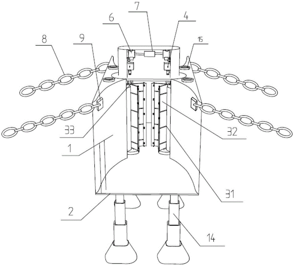
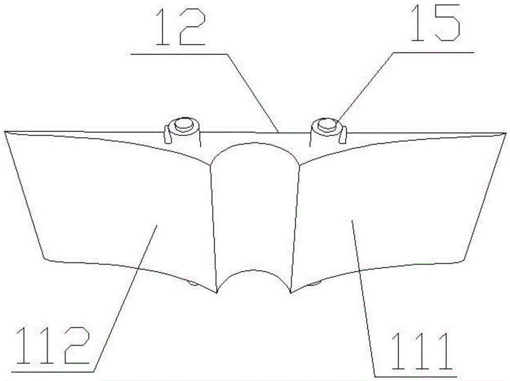
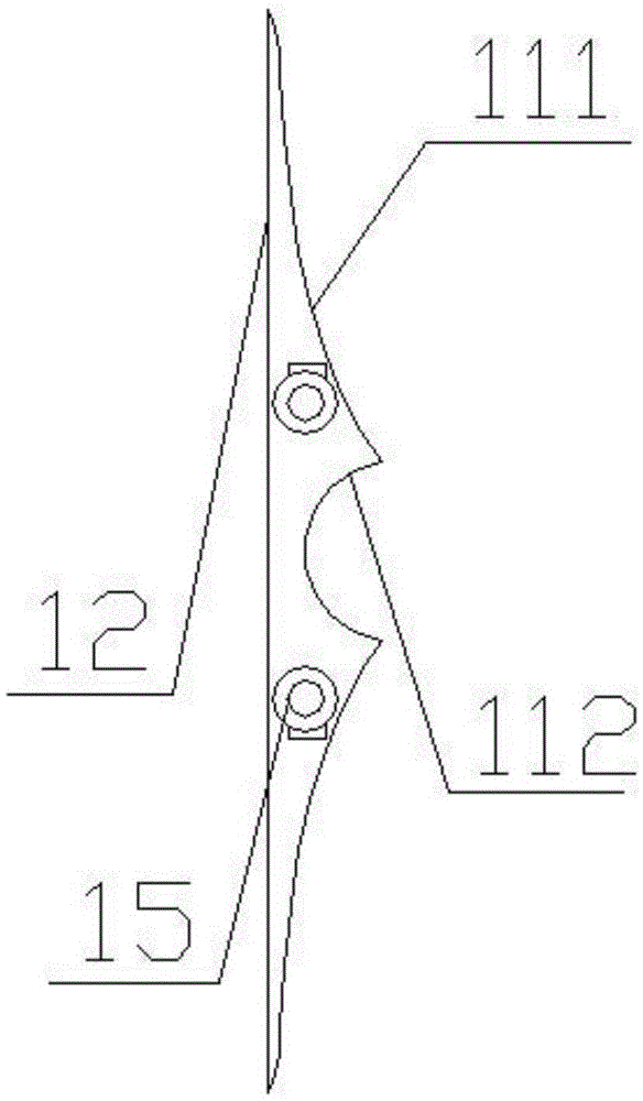
[0023] figure 1 It is a perspective view of the symmetrical semi-shading tidal current energy generating device, which consists of a semi-shading device 1, a power generating device and telescopic legs. Such as figure 2 and image 3 The semi-shielding device 1 shown is a unilateral semi-shielding device, which includes a flow guiding part 111 and an impeller matching part 112. The semi-shielding device has a characteristic profile design, and has both shielding and flow guiding functions. Its interior is a cavity type floating body structure, and the upper and lower surfaces of the shell are respectively opened with holes 15, which can be injected with ballast water and air to control the buoyancy of the shell in water. Side, its upper and lower surfaces are planar structures parallel to the horizontal plane and the holes 15 for injecting ballast water are located on the upper and lower surfaces respectively; the side of the semi-shielding device 1 has four walls, one of wh...


PUM


Abstract

The invention discloses a symmetrical semi-shading type tidal current energy generation device. The generation device is composed of a semi-shading device, a generation device body and telescopic pile legs. A current guide part of the semi-shading device is provided with a special shaped line design. The whole device is fixed to the seabed through the telescopic pile legs after sinking to the appropriate depth. The upper portion of the semi-shading device is provided with a cuboid-shaped motor protective cover. A change speed gear box and a generator are arranged inside the protective cover. The generation device body comprises vertical axis water turbines comprising flap type composite blades, the change speed gear box and a generator set, wherein the axis centers of the flap type vertical axis water turbines are arranged into a line on a straight line, and one bilateral type semi-shading device is installed between every two flap type vertical axis water turbines. Through two vertical impellers and the symmetrical distribution of shading current guide shells of the two vertical impellers, the conflux effect is strengthened, and the utilization ratio of tidal current energy is improved. Modularized manufacturing and lateral spreading are facilitated through the symmetrical semi-shading type tidal current energy generation device, therefore, the generation device can be installed and applied in a wide water area in an array mode, and accordingly large-scale power generating through the tidal current energy is achieved.

Description

technical field [0001] The invention relates to the technical field of tidal current energy generation, in particular to a semi-shading device and a tidal current energy generating set using the semi-shading device. Background technique [0002] The tidal current mainly refers to the regular sea current generated along with the tidal phenomenon, and the tidal current changes its magnitude and direction twice a day. Tidal energy is different from tide. Tidal is the rise and fall of seawater caused by high tide and ebb tide. Tidal current is the horizontal movement of seawater. The energy carried by tide is potential energy, which can be utilized by damming and storing water for power generation, while tidal energy power generation is Directly use tidal currents to impact mechanical devices such as impellers to drive generators to generate electricity. [0003] Compared with conventional energy sources, tidal current energy has the following advantages: clean and renewable; l...

Claims


Application Information

Patent Timeline
Patent Type & Authority Applications(China)
IPC IPC(8): F03B3/18F03B13/00F03B3/12
CPCF03B3/121F03B3/18F03B13/00Y02E10/20Y02P70/50
Inventor 王化明吕俊吴健
Owner ZHEJIANG OCEAN UNIV
Why Eureka
Eureka Blog
Learn More