Uniform load sliding bearing

A technology of sliding bearings and bearing pads, which is applied in the field of load-balanced sliding bearings, can solve problems affecting bearing capacity, temperature rise of thrust pads, jamming of pad bodies and pad sleeves, etc., so as to improve safety and reliability, reduce Oil film pressure and tile temperature, the effect of reducing frictional resistance

Active Publication Date: 2016-04-06
DONGFANG TURBINE CO LTD
View PDF15 Cites 5 Cited by
  • Summary
  • Abstract
  • Description
  • Claims
  • Application Information

AI Technical Summary

Problems solved by technology

[0002] During the operation of the sliding bearing, due to the static deflection of the rotor due to its own gravity and the misalignment of the installation, the centerline of the journal and the centerline of the bearing do not coincide, resulting in deflection in the axial direction, causing the support bearing and journal Axial rubbing occurs; and during operation, the oil film pressure of the bearing is asymmetrical along the axial direction, so that the temperature sensor installed in the middle of the axial position of the bearing cannot capture the highest bush temperature of the bearing bush, so the health status of the bearing cannot be accurately monitored
For thrust-supported combined bearings, the deflection of the journal affects the load distribution of each thrust pad, which in turn causes the temperature rise of the heavily loaded thrust pad to be too high
In order to make the bearing bush follow the deflection of the journal so as to ensure the centering of the journal and the bearing, the support bearing or the thrust support joint bearing, a structure with a spherical pair is often used at present. The characteristic of this structure is that the mating surface of the bearing bush is an outer spherical surface and The mating surface of the bushing supporting the bearing bush is an inner spherical surface; the disadvantage is that the bushing is constrained by the bearing seat, and the radius of curvature changes little after being stressed; due to the high rigidity of the bearing bush, the radius of curvature changes little after being stressed
Therefore, in actual work, it often occurs that the pad body and the pad sleeve are jammed, and the accurate alignment between the journal and the pad body cannot be maintained, thereby affecting the bearing capacity.

Method used


Image

  • Uniform load sliding bearing
  • Uniform load sliding bearing
  • Uniform load sliding bearing

Examples


Embodiment 1

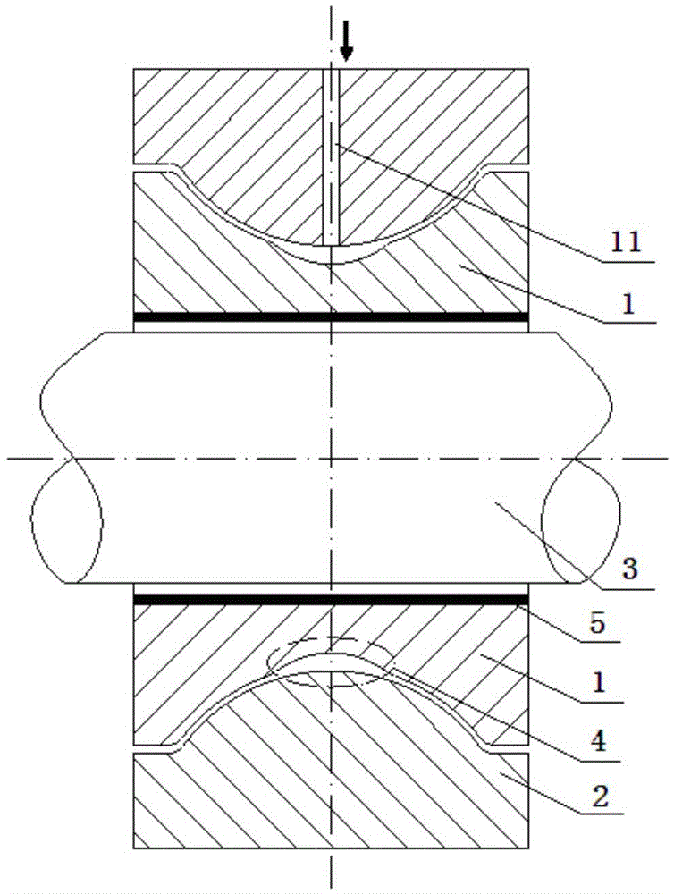
[0019] like figure 1 , Figure 5 As shown, a load-sharing sliding bearing is characterized in that it includes an inner spherical bearing bush 1 and an outer spherical bushing 2; the inner spherical bearing bush 1 and the outer spherical bushing 2 form a spherical fit, and the inner spherical bearing bush 1 There is a rigidity-reducing groove 4 on the spherical surface; the inner spherical bearing 1 is the upper and lower halves of the split support bearing; the rigidity-reducing groove 4 is an annular groove with a cross-sectional shape of an arc shape, and the annular angle β is 360° ; There is space for storing lubricating oil in the annular gap between the inner spherical bearing 1 and the outer spherical bushing 2 in the rigidity-reducing groove 4 ;

Embodiment 2

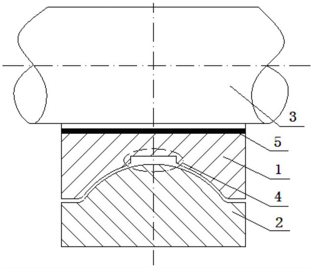
[0021] like figure 2 , Figure 5 As shown, a load-sharing sliding bearing is characterized in that it includes an inner spherical bearing bush 1 and an outer spherical bushing 2; the inner spherical bearing bush 1 and the outer spherical bushing 2 form a spherical fit, and the inner spherical bearing bush 1 There is a rigidity-reducing groove 4 on the spherical surface; the inner spherical bearing 1 is the upper and lower halves of the split support bearing; the rigidity-reducing groove 4 is a rectangular annular groove with a cross-sectional shape, and the annular angle β is 180°; There is a lubricating oil storage space in the annular gap of the rigidity-reducing groove 4 between the inner spherical bearing bush 1 and the outer spherical bushing 2 .

Embodiment 3

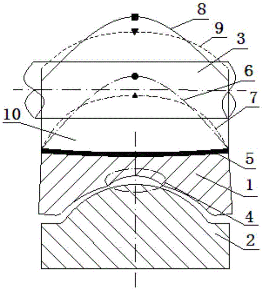
[0023] like image 3 , Figure 5 As shown, a load-sharing sliding bearing is characterized in that it includes an inner spherical bearing bush 1 and an outer spherical bushing 2; the inner spherical bearing bush 1 and the outer spherical bushing 2 form a spherical fit, and the inner spherical bearing bush 1 There is a rigidity-reducing groove 4 on the spherical surface; the inner spherical bearing 1 is the upper and lower halves of the split support bearing; the rigidity-reducing groove 4 is an annular groove with a cross-sectional shape of a spline curve, and the annular angle β is 120° °; There is a space for storing grease in the annular gap between the inner spherical bearing bush 1 and the outer spherical bushing 2 in the rigidity-reducing groove 4 .

[0024] like Figure 4 As shown, the rotary groove designed at the axial center position of the bearing pad with an inner spherical surface in the present invention is the rigidity-reducing groove 4 that reduces the rigidi...


PUM


Abstract

The invention discloses a uniform load sliding bearing. The uniform load sliding bearing comprises an inner spherical surface bearing bush and an outer spherical surface bearing bush; and the inner spherical surface bearing bush and the outer spherical surface bearing bush form spherical surface fit, and a stiffness reduction groove is formed in an inner spherical surface of the inner spherical surface bearing bush. Through increase of the curvature radius of the inner spherical surface of the inner spherical surface bearing bush matched with the outer spherical surface bearing bush and lubricating oil stored in the stiffness reduction groove, deflection of the bearing bushes along with a shaft neck is facilitated, frictional resistance during deflection of the bearing bushes is reduced, and clamping between the uniform load sliding bearing and the bearing bushes during deflection of the bearing bushes is omitted; a saddle-shaped axial gap is formed between the bearing bushes and the shaft neck, the oil film pressure and the bush temperature of the middle portion of the bearing bushes are decreased, and the safety and the reliability of the service of a unit are improved.

Description

technical field [0001] The invention belongs to the technical field of sliding bearings, in particular to a load balancing sliding bearing. Background technique [0002] During the operation of the sliding bearing, due to the static deflection of the rotor due to its own gravity and the misalignment of the installation, the centerline of the journal and the centerline of the bearing do not coincide, resulting in deflection in the axial direction, causing the support bearing and journal Axial rubbing occurs; and during operation, the oil film pressure of the bearing is asymmetrical along the axial direction, so that the temperature sensor installed in the middle of the axial position of the bearing cannot capture the highest bush temperature of the bearing bush, so the health status of the bearing cannot be accurately monitored . For thrust-supported combined bearings, the deflection of the journal affects the load distribution of each thrust pad, and then the temperature ri...

Claims


Application Information

Patent Timeline
Patent Type & Authority Applications(China)
IPC IPC(8): F16C23/04F16C33/10
CPCF16C23/043F16C33/102F16C33/1025
Inventor 彭林董卫红廖上斌崔颖马廿罗小川段永红汪磊王英权卢天海王彪黄俊杰牟余彭章龙
Owner DONGFANG TURBINE CO LTD
Why Eureka
Try Eureka