

Flash tank and refrigeration system with same
A refrigeration system and flasher technology, which is applied in the direction of refrigerators, refrigeration components, refrigeration and liquefaction, etc., can solve the problems of automatic adjustment, etc., and achieve the effect of multi-capacity output, control of exhaust temperature, and high COP
- Summary
- Abstract
- Description
- Claims
- Application Information
AI Technical Summary
Problems solved by technology
Method used
Image

Examples
Embodiment Construction
[0033] The present invention will be further described below in conjunction with the accompanying drawings and specific embodiments.
[0034] In existing applications, the liquid level of the flasher cannot be automatically adjusted without electronic control. In addition, the dryness of the jet cannot be guaranteed, and the functional characteristics of the flasher and the heat exchanger cannot be combined. The existing flasher has a low integration level, does not have a liquid level control function, and cannot guarantee sufficient jet dryness.
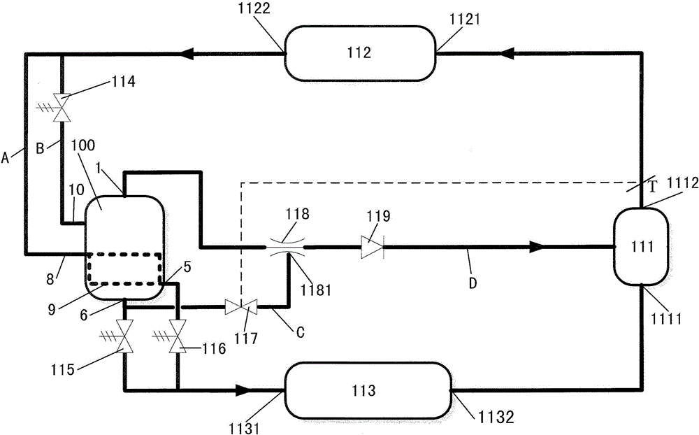
[0035] like figure 1 As shown, the refrigeration system according to the embodiment of the present invention may include: a compressor 111, a flasher 100, an ejector 118, a condenser 112, an evaporator 113, and pipelines connecting the above components. The ejector 118 is connected between the gaseous medium outlet 1 of the flasher 100 and the compressor 111 .
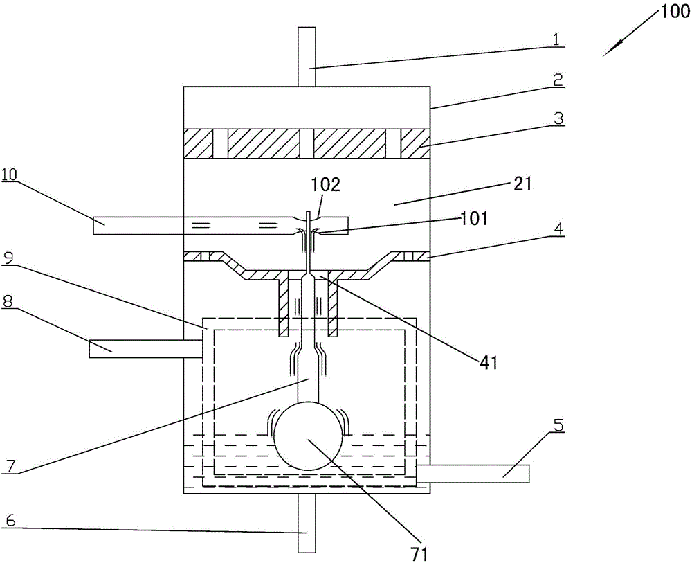
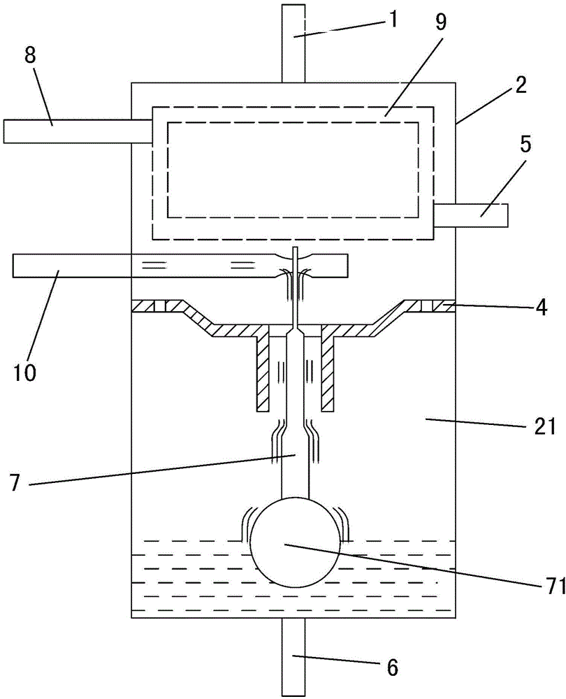
[0036] figure 2 is a schematic diagram of a flasher according to ...
PUM
 Abstract
Description
Claims
Application Information