
Movable ocean engineering flexible pipe cable torsion test device

A technology for marine engineering and torsion testing, applied in the direction of measuring devices, strength characteristics, instruments, etc., can solve the problems of not being able to control the loading speed well, uneven changes in torque size, affecting the stability of test results, etc., and achieve convenient control methods. , save material, improve the effect of stability

Active Publication Date: 2016-04-06
DALIAN UNIV OF TECH
View PDF7 Cites 14 Cited by
  • Summary
  • Abstract
  • Description
  • Claims
  • Application Information

AI Technical Summary

Problems solved by technology

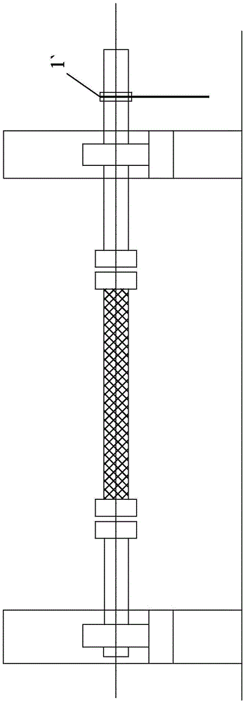
There are many disadvantages in this torque loading method: 1. For the umbilical structure with small torsional rigidity, it is relatively convenient to use the chain hoist 1`; A larger bending moment can only be achieved with a longer transmission arm, which is obviously not conducive to the implementation of limited space in the laboratory
2. At the same time, as the rotation angle increases during the loading process, the direction of the force exerted by the chain hoist 1` will continue to change along the direction of the rope, so the uneven variation of its torque will affect the stability of the test results
3. Relying on the loading method of chain block 1`, manual force can only be applied intermittently, so the loading speed cannot be well controlled
At the same time, due to the structural characteristics of the chain block 1`, a certain rebound will occur after each force is applied, which brings great inconvenience to the later data processing

Method used


Image

  • Movable ocean engineering flexible pipe cable torsion test device
  • Movable ocean engineering flexible pipe cable torsion test device
  • Movable ocean engineering flexible pipe cable torsion test device

Examples


Embodiment Construction

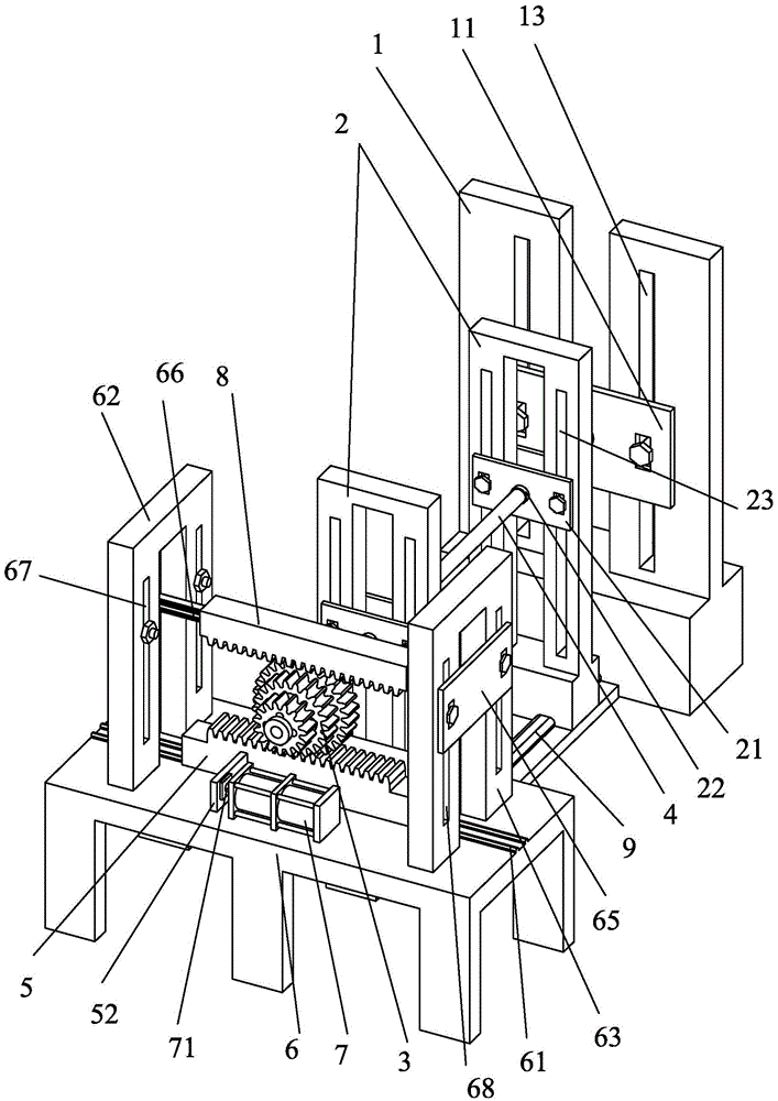
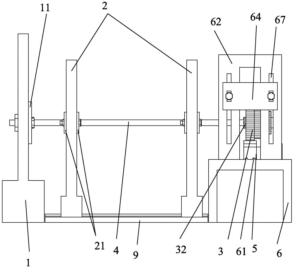
[0044] Such as Figure 2-Figure 9 As shown, a movable torsion test device for flexible umbilical cables in marine engineering includes a fixed-end bracket 1, two fixed brackets 2 and a multi-stage gear 3 arranged in sequence along a straight line,

[0045] The fixed end bracket 1 includes a fixed plate I11, and the fixed plate I11 is provided with a pipe cable fixing flange I12,

[0046] The fixed bracket 2 includes two fixed plates II21 respectively located on the front and rear surfaces of the fixed bracket 2, and the fixed plate II21 is provided with a sleeve 22 through which the umbilical cable 4 passes.

[0047] The multi-stage gear 3 is connected to the support platform 6 through the rack I5, the support platform 6 is provided with a guide rail I61, and the end of the rack I5 far away from the multi-stage gear 3 is provided with a The guide groove I51, the extension direction of the guide rail I61 is perpendicular to the arrangement direction of the fixed end bracket 1,...


PUM


Abstract

The invention discloses a movable ocean engineering flexible pipe cable torsion test device. The movable ocean engineering flexible pipe cable torsion test device comprises a fixing end support, two fixing supports and a multi-stage gear, wherein the fixing end support, the two fixing supports and the multi-stage gear are sequentially and linearly arranged. The multi-stage gear is connected with a supporting table through a rack I. The supporting table is provided with an actuator and is further provided with a rack support I and a rack support II. The rack support I comprises a rack fixing plate I. The rack support II comprises a rack fixing plate II. Guide rails II parallel with guide rails I are arranged between the rack fixing plate I and the rack fixing plate II and are provided with a rack II pressing the multi-stage gear on the rack I. The lower ends of the fixing supports are provided with guide rails III perpendicular to the guide rails I. According to the movable ocean engineering flexible pipe cable torsion test device, the actuator drives the racks to complete rotation of the gear, operation is more convenient, labor is saved, operation is precise, torque loading is more flexible, and the movable ocean engineering flexible pipe cable torsion test device can be used for torsion testing of various pipe cables.

Description

technical field [0001] The invention relates to a test device, in particular to a movable torsion test device for flexible umbilical cables in marine engineering. Background technique [0002] Flexible umbilical cables for offshore engineering are widely used in offshore oil and gas production. Typical umbilical cables include: 1. The submarine cable that provides power and electricity for the submarine development device; 2. The umbilical cable that is connected between the water platform and the submarine manifold to play a control function; 3. Used to transport the extracted oil and gas to Flexible piping for storage equipment. These flexible umbilical cables are an important part of key equipment for the development of offshore oil and gas resources, and are the "lifeline" to ensure the normal operation of oil and gas fields. Due to the influence of factors such as working load, floating body movement and complex marine environment, it is easy to cause failure of vario...

Claims


Application Information

Patent Timeline
IPC IPC(8): G01N3/26G01N3/02
CPCG01N3/02G01N3/26
Inventor 杨志勋杨钰城阎军卢青针岳前进陈金龙吴尚华尹原超
Owner DALIAN UNIV OF TECH
Learn More