
Control of an aircraft as a thrust-vectored pendulum in vertical, horizontal and all flight transitional modes thereof

a control system and aircraft technology, applied in the field of aircraft, can solve the problems of inherently unstable aircraft, counterbalance the static forward center of mass, and inability to stabilize fixed wing aircraft, and achieve the effect of reducing the net gravitational for

Inactive Publication Date: 2005-03-08
SASH THOMAS
View PDF17 Cites 20 Cited by
  • Summary
  • Abstract
  • Description
  • Claims
  • Application Information

AI Technical Summary

Benefits of technology

Another object of this invention is to provide an improved method of control for aircraft whether in vertical flight, horizontal flight, or any transition mode, thereof.
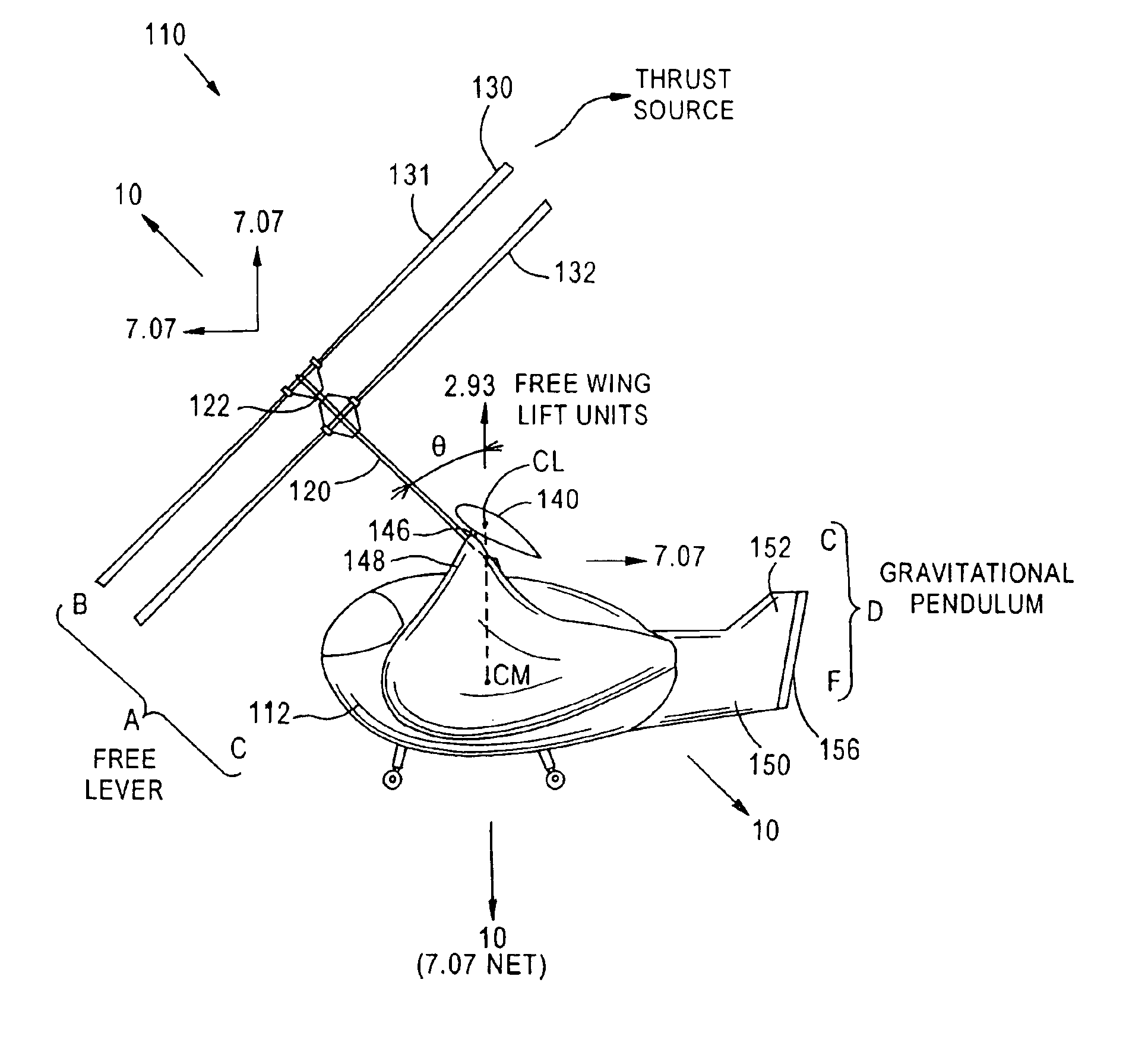
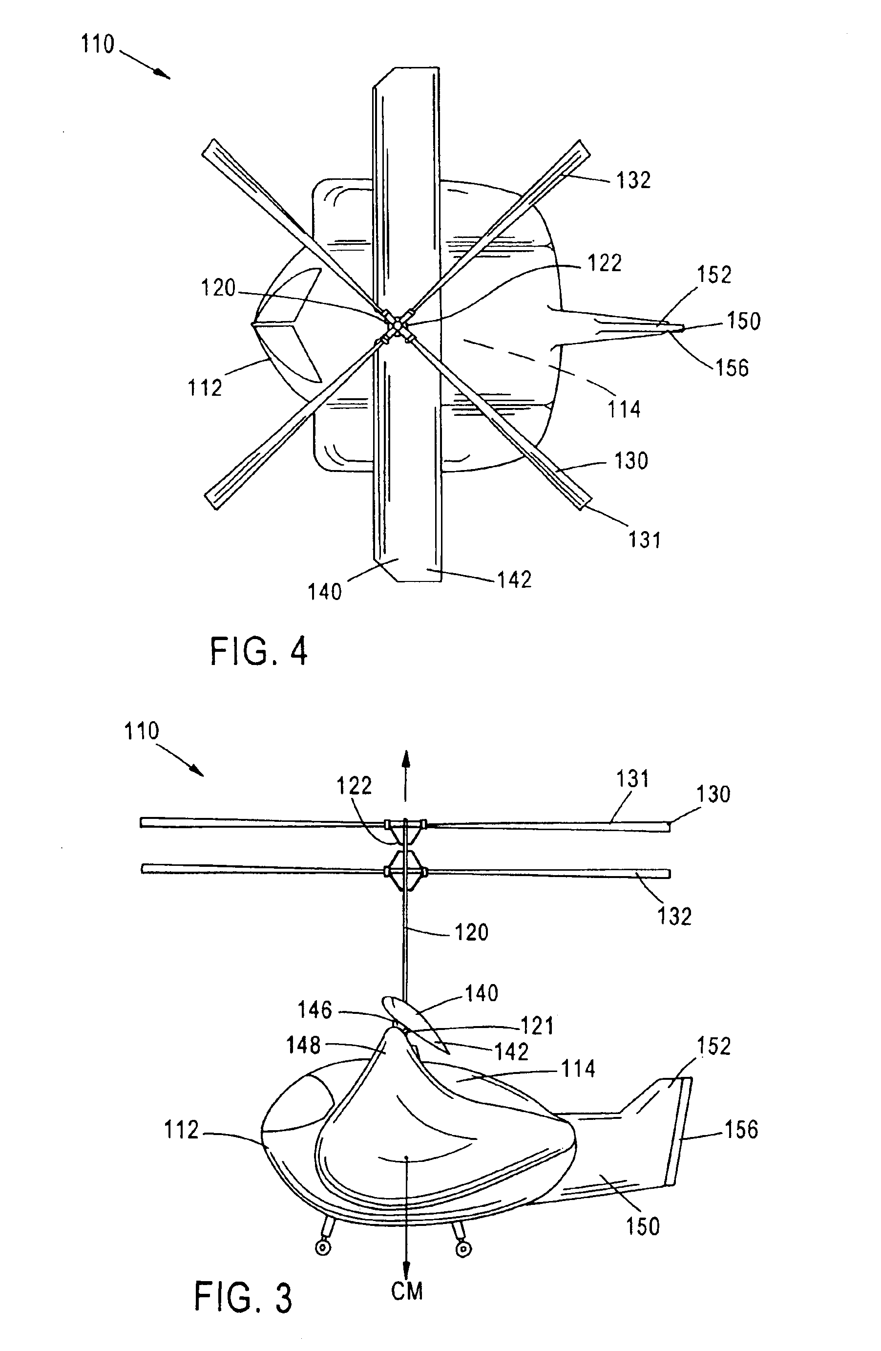
In accordance with another aspect of the present invention, a wing, which is preferably a free wing, is incorporated into the inventive aircraft. Preferably, the free wing is attached with its center of lift at or above, and vertically approximate to the center of mass of the inventive aircraft. The freewing is free to pivot without pilot intervention about a spanwise axis at the point of attachment. The free wing contributes to the smooth transition from vertical to horizontal flight. It is within the scope of the present invention, in another embodiment, to provide a pivoting wing which can also be mechanically forced to assume a suitable angle of attack in response to the vectored thrust.
In accordance with still another aspect, the invention utilizes a common propulsion system for both vertical and horizontal flight and which method results in an aircraft which is inherently stable in both vertical and horizontal flight and all transitional modes of flight. The invention utilizes a dual pendulum arrangement, the first being a gravitational, or static, pendulum and the second being a lift / drag pendulum created by airflow about the wing and aircraft. The lift / drag pendulum is of a varying or dynamic nature since its force varies upon the speed of the airflow about the wing and aircraft. The effect of the lift / drag pendulum is to reduce the net gravitational forces acting upon the proximal end of the free lever shaft to zero in horizontal flight. The byproduct of the vertical lift produced by the wing is drag in the horizontal which creates a drag pendulum opposed by the thrust of the engine.

Problems solved by technology

If it did not, and the airplane wings entered a stalled condition, there would be no means of lowering the nose of the aircraft to regain flying speed and therefore the aircraft would be inherently unstable.
This fulcrum arrangement provides downward pressure from the tail of the aircraft in flight which counterbalances the static forward center of mass.
A fixed wing aircraft is inherently unstable below the stall speed of the particular aircraft.
Compared with a fixed wing aircraft, the rotary wing aircraft has the disadvantage of inefficient cross country travel, the inability for high speed horizontal flight, and lower operational altitudes.
The fixed wing aircraft has the disadvantage of substantial takeoff and landing speed thus requiring a substantial runway space for takeoff and landings.
In addition, the fixed wing aircraft is incapable of flight below operating airspeeds or hovering maneuvers due to the loss of lift over the fixed wing of the aircraft due to insufficient speed.
Those attempts which have tried to create a heliplane, or some similar conversion of a helicopter into an airplane by attaching a wing to the vehicle, have been quite unsuccessful.
The spinning rotor creates enormous drag at high forward speeds, and one still has all the problems with the forward and rearward sweeping rotor blades and the problem that the center of mass remains inherently different from an airplane.
All of the previous art has failed to address the fundamental difference in the center of mass, both dynamic and static, between existing vertical flight aircraft (helicopters) and existing horizontal flight aircraft (airplanes).
All of the previous art has failed to address the fundamental difference in efficiency between the forward movement of vertical flight aircraft (helicopters) and the forward movement of existing horizontal flight aircraft (airplanes).
Conversely, all of the previous art has failed to address the fundamental difference in efficiency between the vertical movement of vertical flight aircraft (helicopters) and the vertical movement of existing horizontal flight aircraft (airplanes).
Although many of the United States patents referenced in this application, and other patents of which I am aware, have attempted to provide a hybrid aircraft that has the advantages of a fixed wing aircraft and a rotary wing aircraft, the aforementioned United States patents fail to accomplish this task.
One fundamental reason why the hybrid aircrafts of prior art have failed to accomplish this task is due to a period of instability encountered during the period of transition between the operation as a fixed wing aircraft and the operation as a rotary wing aircraft.
The movement of the center of mass of the hybrid aircraft creates a fundamental instability in the operation of the hybrid aircraft making the hybrid aircraft difficult to control during this transition period.
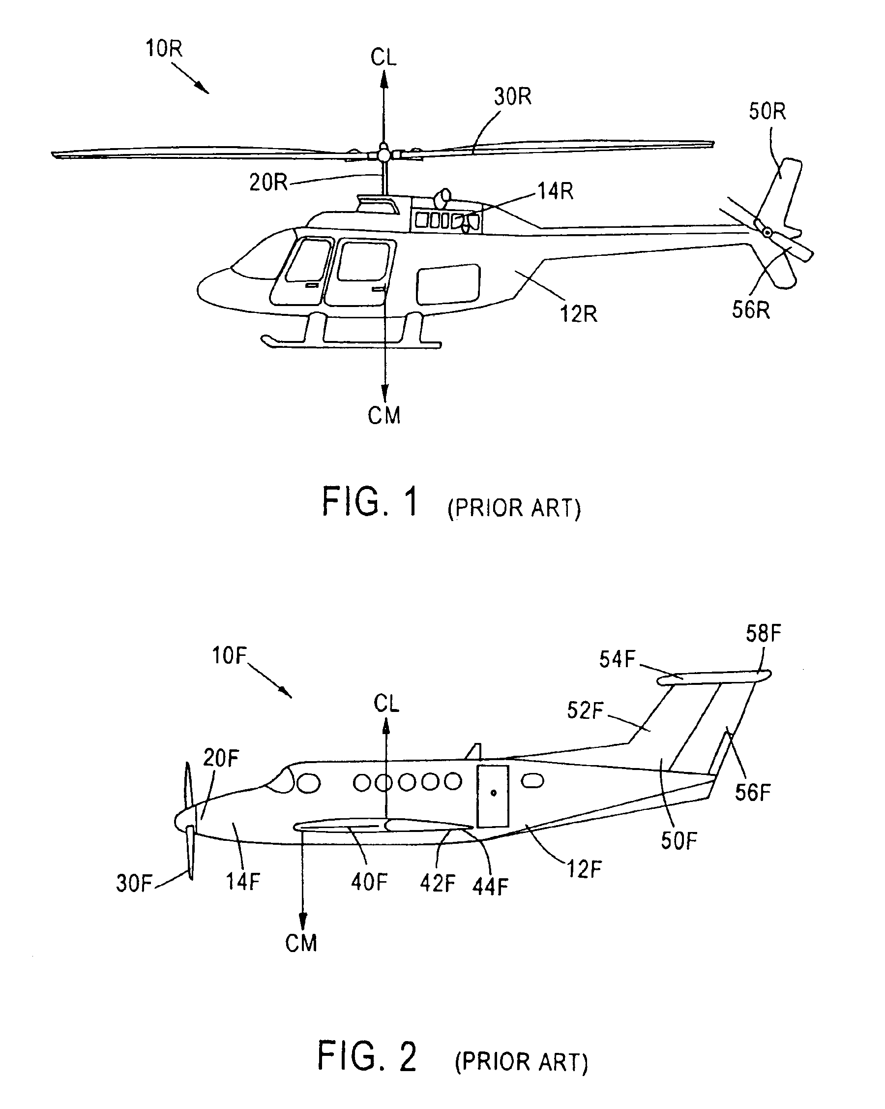
This is a fundamental limitation of a rotary wing aircraft 10R.
The airflow then separates from the upper surface of the wing, thereby destroying lift and control of the aircraft.
Unfortunately, the hybrid aircraft of such prior art could not solve the problem of the fundamental difference in the position of the center of mass (CM) between the rotary wing aircraft 10R and the fixed wing aircraft 10F.

Method used


Image

  • Control of an aircraft as a thrust-vectored pendulum in vertical, horizontal and all flight transitional modes thereof
  • Control of an aircraft as a thrust-vectored pendulum in vertical, horizontal and all flight transitional modes thereof
  • Control of an aircraft as a thrust-vectored pendulum in vertical, horizontal and all flight transitional modes thereof

Examples


second embodiment

FIGS. 15-23 are illustrations of the present invention wherein the rotor is replaced with jet engines 214 which can also be prop engines, etc. In this embodiment, two free lever shafts 220 each supporting one jet engine 214 are used. It is, however, within the scope of the present invention to provide any other number of free lever shafts and jet engines.

Each jet engine 114 is coupled through one free lever shaft 220 extending between a proximal end 221 and a distal end 222. The proximal end 221 is pivotally supported by the fuselage 212 via elements 260, 270.

first embodiment

The improved aircraft 210 in this embodiment also includes a wing 240, which is preferably a free wing like the free wing illustrated in FIGS. 3-11 of the Preferably, the free wing 240 includes plural ailerons 242 for lateral control in horizontal flight of the improved aircraft. The angle of attack of the free wing 240 may be adjusted and the lateral control provided during horizontal flight through the use of plural elevons. Freewing 240 is connected to a supporting portion 248 of fuselage 212 for free rotation about a spanwise axis 246. The improved aircraft 210 further includes tail section 250 rigidly secured to the fuselage 212 having a vertical stabilizer 252 and rudder 256.

The improved aircraft 210 functions similarly to the aircraft 110 of the first embodiment. In particular, when the thrust generated by jet engines 214 is vectored, e.g., as shown in FIG. 20, free lever shaft 220 is caused to freely pivot to seek a new dynamic equilibrium as illustrated in FIG. 21. Prefera...

third embodiment

FIGS. 24-30 show the present invention which is basically similar to the first embodiment. In particular, aircraft 300 is illustrated as being stationary on ground 2400 prior to taking off. Aircraft 300 includes fuselage 2415, free wing 2414, wheels or landing gear 2402, 2404, and free lever shaft 2416 having a proximal end pivotally supported by the fuselage and a distal end supporting rotor 2418.

This embodiment is different from the first embodiment in that secondary lateral and ventral dynamic flight control surfaces, e.g., 2709, are attached to the free lever shaft between the distal and proximal ends, 2422, 2421 of said shaft, and, preferably, towards the distal end 2422 as best seen in FIG. 27.

The lateral dynamic flight control surface may be a wing with control surfaces, a pivotable wing, or in accordance with a preferred embodiment of the present invention, a freewing 2708 with control surfaces 2709. A secondary free wing is preferred because in vertical or near vertical fli...


PUM


Abstract

An improved aircraft includes a thrust source, a wing, and a boom functioning as a “free lever” and having a distal end upon which the thrust is acting and a proximal end about which the boom is freely rotatable to balance forces acting on the proximal and distal ends of the boom. The proximal end is pivotably mounted at or below the center of lift of the wing and above the center of mass of the aircraft. The distal end is located above the center of mass of the aircraft, when the lever is in the vertical position to establish a gravity pendulum, and forward of the center of drag of the aircraft, when the lever is in the horizontal position, to establish a drag pendulum. All transition flight is a resolution of the force vectors of the two pendulums. A director adjusts the vertical and horizontal thrust components of the propulsion system.

Description

FIELD OF THE INVENTIONThis invention relates to aircraft and more particularly to an improved aircraft incorporating the benefits of a vertical takeoff and landing aircraft, e.g., a rotary wing aircraft, and an airplane, e.g., a fixed wing or a flexible wing aircraft, and to an improved aircraft control method providing for inherently stable flight in both vertical and horizontal flight, and all transition modes thereof.BACKGROUND ARTThroughout the twentieth century, the prior art has developed for various types of aircraft. In general, the aircraft can be divided into two basic types of aircraft. The first type of aircraft is commonly referred to as a fixed wing aircraft whereas the second type of aircraft is commonly referred to as a rotary wing aircraft.In fixed wing aircraft, an engine may transmit output to a horizontally extending shaft for rotating a propeller to provide the horizontal thrust to the fixed wing aircraft. In the alternative, the engine may be a jet engine provi...

Claims


Application Information

Patent Timeline
IPC IPC(8): B64C27/00B64C27/52B64C29/00B64C3/38B64C27/28B64C3/00
CPCB64C3/385B64C27/28B64C29/0033B64C29/0075B64C27/52Y02T50/145Y02T50/10
Inventor SASH, THOMAS
Owner SASH THOMAS
Learn More