
Multi-view remote sensing image fusion method

A remote sensing image fusion and remote sensing image technology, which is applied in the field of geographic information, can solve the problem of low registration accuracy, and achieve the effect of high fusion accuracy and high precision

Inactive Publication Date: 2016-04-06
YUNNAN NORMAL UNIV
View PDF3 Cites 7 Cited by
  • Summary
  • Abstract
  • Description
  • Claims
  • Application Information

AI Technical Summary

Problems solved by technology

[0003] The purpose of the present invention is to solve the problem that the existing registration technology has limitations in the registration of non-rigid transformations caused by ground fluctuations or multi-view changes in images, resulting in low registration accuracy
A multi-view remote sensing image fusion method is now provided

Method used


Image

  • Multi-view remote sensing image fusion method
  • Multi-view remote sensing image fusion method
  • Multi-view remote sensing image fusion method

Examples


specific Embodiment approach 1

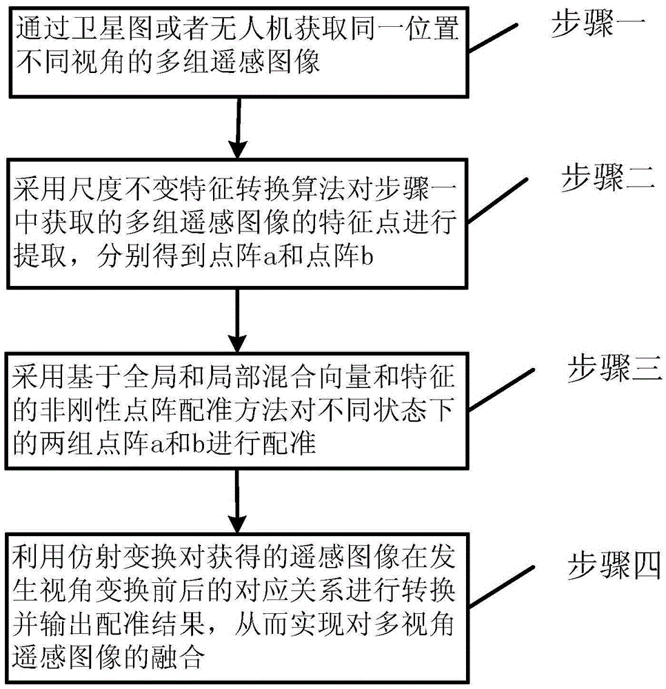
[0014] Specific implementation mode one: refer to figure 1 Specifically illustrate this embodiment, the multi-view remote sensing image fusion method described in this embodiment, the method includes the following steps:

[0015] Step 1. Obtain multiple sets of remote sensing images of the same location with different perspectives through satellite images or drones,

[0016] Step 2. Using the scale-invariant feature conversion algorithm to extract the feature points of multiple groups of remote sensing images acquired in step 1, and obtain lattice a and lattice b respectively,

[0017] Step 3. Using a non-rigid lattice registration method based on global and local mixed vectors and features to register two sets of lattices a and b in different states, the registration process is as follows:

[0018] Step 31. First create a deformable proxy lattice a w , in each step of the iteration, get a w Corresponding point b in lattice b c , where a w The initial state of is equal to...

specific Embodiment approach 2

[0028] Embodiment 2: This embodiment is to further explain the multi-view remote sensing image fusion method described in Embodiment 1. In this embodiment, the equation of the global and local mixed vector and feature in step 3 is:

[0029] According to the formula:

[0030] (Formula 1),

[0031] Obtaining the Global Structural Feature Difference Matrix Each element value in the matrix is ​​two vectors and The modulus after subtraction,

[0032] In the formula, for point a i to point a k the geometric vector of for point b j to b k The geometric vector of , i and j are both positive integers, n and m are the upper bounds in the formula,

[0033] According to the formula:

[0034] (Formula 2),

[0035] Obtain local structural feature difference matrix

[0036] In the formula, K is the number of neighboring points, n(a i ) k for point a i The kth neighbor point of , n(b j ) k for point b j The kth neighbor point of , T is a translation function,...

specific Embodiment approach 3

[0037] Embodiment 3: This embodiment is to further explain the multi-view remote sensing image fusion method described in Embodiment 2. In this embodiment, in step 31, a deformable proxy lattice a is first created w , in each step of the iteration, get a w The steps of corresponding point bc in lattice b are:

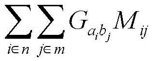
[0038] According to the energy optimization equation:

[0039] E ( M ) = ( Σ i ∈ n Σ j ∈ m G a i b j + α Σ i ∈ n ...


PUM


Abstract

The invention discloses a multi-view remote sensing image fusion method, relates to the technical field of geographic information, and aims to solve the problem of low registration precision caused by limitation of registration of non-rigid transformation of an existing registration technology to ground surface fluctuation change or image multi-view change. The method comprises the steps of step 1, obtaining multiple groups of remote sensing images of different view angles in a same position through a satellite map or an unmanned aerial vehicle; step 2, extracting feature points of the multiple groups of the remote sensing images obtained in the step 1 by adopting a scale invariant feature transform algorithm to obtain a dot matrix (a) and a dot matrix (b); and step 3, registering the dot matrixes (a and b) in different states with a non-rigid dot matrix registration method based on global and local hybrid vectors and features, transforming a corresponding relationship of the remote sensing images obtained in the step 3 before and after view transformation by utilizing affine transformation, and outputting a registration result, so as to realize the fusion of the multi-view remote sensing images. The method is used for image fusion of the images during multi-view transformation.

Description

technical field [0001] The invention relates to a multi-view remote sensing image fusion method and belongs to the technical field of geographic information. Background technique [0002] At present, multi-view remote sensing image fusion technology plays an important role in the fields of geographic information systems such as aerial survey, oblique shadow measurement, new navigation and map update. However, some non-rigid transformations will occur when the ground relief changes or the image changes from multiple perspectives. The current registration technology will be significantly affected in accuracy and has certain limitations. Contents of the invention [0003] The purpose of the present invention is to solve the problem that the existing registration technology has limitations in the registration of non-rigid transformations caused by ground fluctuations or multi-angle changes in images, resulting in low registration accuracy. A multi-view remote sensing image fu...

Claims


Application Information

Patent Timeline
IPC IPC(8): G06T7/00
CPCG06T2207/10032
Inventor 杨扬杨昆潘安宁吴芳青罗毅王加胜
Owner YUNNAN NORMAL UNIV
Learn More