Wireless charging system and wireless charging device thereof

A wireless charging and charging circuit technology, applied in battery circuit devices, circuit devices, current collectors, etc., can solve problems such as reducing battery charging speed, shortening battery life, and accumulating charges on positive and negative plates, and improving battery life, The effect of fast charging

Active Publication Date: 2018-06-19
潘子恒
View PDF4 Cites 0 Cited by
  • Summary
  • Abstract
  • Description
  • Claims
  • Application Information

AI Technical Summary

Problems solved by technology

[0011] 3. Electrochemical polarization phenomenon: During the charging process of the battery, the external power supply continuously obtains electrons from the positive plate of the battery and transports them to the negative plate, and the active material on the positive and negative plates reacts electrochemically with the electrolyte, but due to the electrochemical reaction The speed is much smaller than the speed of electron movement, therefore, charge accumulation is formed on the positive and negative plates
[0012] All three polarization phenomena will affect the charging process, and the result is that charging requires more power and more time, especially the electrochemical polarization phenomenon causes short-term "passivation" around the battery electrodes in actual situations This phenomenon greatly reduces the charging speed of the battery and shortens the service life of the battery. Therefore, how to overcome the shortcomings of the existing charging methods, save time and energy for battery charging, and prolong the service life of the battery has become an urgent problem to be solved.
[0013] In summary, when there is a charging demand, the existing technology is difficult to simultaneously meet the requirements of wireless charging convenience, rapidity, and prolonging battery life and battery life of the device to be charged.

Method used


Image

  • Wireless charging system and wireless charging device thereof
  • Wireless charging system and wireless charging device thereof
  • Wireless charging system and wireless charging device thereof

Examples


Embodiment Construction

[0036] In order to make the above objects, features and advantages of the present invention more comprehensible, specific embodiments of the present invention will be described in detail below in conjunction with the accompanying drawings.

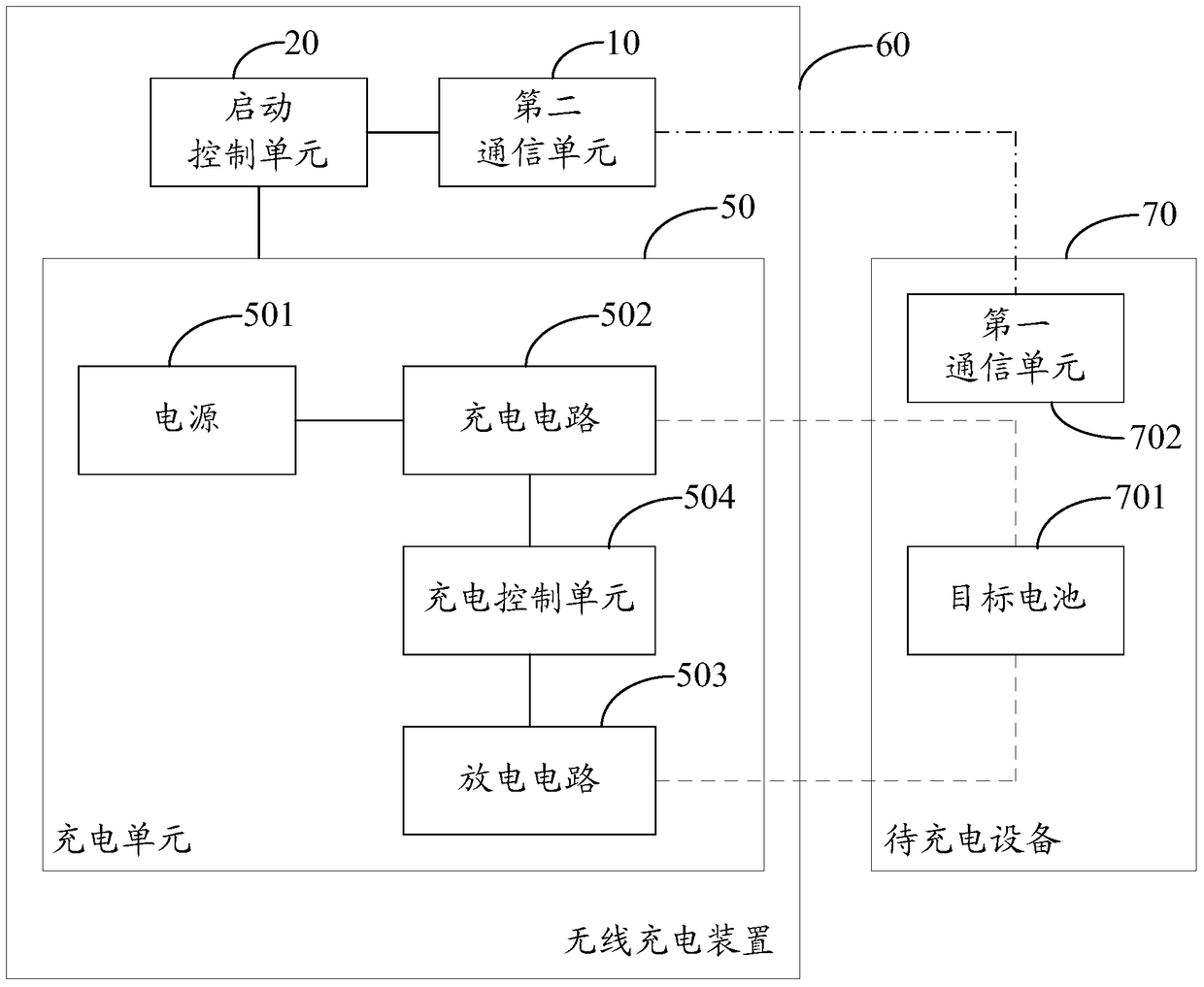
[0037] In order to simultaneously meet the requirements of convenience and rapidity of wireless charging of the device to be charged, as well as prolonging battery life and battery life, this embodiment provides a wireless charging system. Such as figure 1 As shown, the wireless charging system includes a device to be charged 70 and a wireless charging device 60; the device to be charged 70 includes a target battery 701 that supports wireless charging and a first communication unit 702; the wireless charging device 60 includes a charging unit 50 , start the control unit 20 and the second communication unit 10; the first communication unit 702 is adapted to send a wireless signal containing the identity information of the device to be charg...


PUM


Abstract

The invention provides a wireless charging system and a wireless charging device thereof. The wireless charging system comprises equipment to be charged and the wireless charging device, the equipment to be charged comprises a target battery and a first communication unit, the target battery supports wireless charging, the wireless charging device comprises a charging unit, a starting control unit and a second communication unit, and the charging unit comprises a power supply, a charging circuit, a discharging circuit and a charging control unit; after the wireless charging device recognizes charging requirements of the equipment to be charged, a target battery charging process comprises a first charging stage, a discharging stage and a second charging stage which are sequential, continuous and circulatory; in the first charging state, the target battery is charged with constant voltage; in the discharging stage, the target battery is discharged with continuously reduced discharging voltage until the voltage is zero; and in the second charging state, the target battery is charged with continuously increased charging voltage until the voltage is constant voltage. The wireless charging system and the wireless charging device thereof can simultaneously meet requirements of convenience of wireless charging, prolongation of endurance time and prolongation of the service life of the battery.

Description

technical field [0001] The invention relates to the technical field of charging, in particular to a wireless charging system and a wireless charging device thereof. Background technique [0002] Wireless charging technology (Wireless charging technology), derived from wireless power transmission technology, low-power wireless charging often adopts electromagnetic induction (such as the Qi method for charging mobile phones), and high-power wireless charging often uses resonance (most electric vehicle charging uses This way) the power supply equipment (charger) transmits energy to the device that uses the electricity, and the device uses the received energy to charge the battery and at the same time for its own operation. Since energy is transmitted between the charger and the power-consuming device by a magnetic field, the two are not connected by wires, so both the charger and the power-consuming device can have no exposed conductive contacts. There are currently four mains...

Claims


Application Information

Patent Timeline
Patent Type & Authority Patents(China)
IPC IPC(8): H02J7/00H02J50/20
CPCH02J7/025
Inventor 潘子恒
Owner 潘子恒
Why Eureka
Try Eureka