
Magnetic fixture and FPC non-reinforced support electronic assembly welding process applying magnetic fixture

An electronic component and magnetic technology, applied in the field of FPC unreinforced support electronic component welding process, can solve the problems of poor air-welding floating height, poor floating height, poor air-welding, etc., to prevent poor air-welding floating height and poor offset , Improve the welding quality and production efficiency of solder joints, and prevent damage to the FPC.

Active Publication Date: 2016-04-06
昆山圆裕电子科技有限公司
View PDF5 Cites 7 Cited by
  • Summary
  • Abstract
  • Description
  • Claims
  • Application Information

AI Technical Summary

Problems solved by technology

[0003] 1. Using the traditional welding process, it is easy to cause abnormal function of the product after welding, that is, failure to conduct and short circuit;
[0004] 2. Poor floating height of empty soldering, because most customers require that there is no need to add add-ons before welding the flexible circuit board, which will lead to uneven bottom of the welding components during welding, resulting in batch empty soldering and poor floating height;
[0005] 3. Poor offset: Because some large parts do not have positioning PIN (locating pin) positioning, direct welding will inevitably lead to a large number of empty welding defects. poor offset;
[0006] 4. Component damage: Using the carrier to directly contact the component to pressurize the production will inevitably increase the risk of bad damage to the component body

Method used


Image

  • Magnetic fixture and FPC non-reinforced support electronic assembly welding process applying magnetic fixture
  • Magnetic fixture and FPC non-reinforced support electronic assembly welding process applying magnetic fixture
  • Magnetic fixture and FPC non-reinforced support electronic assembly welding process applying magnetic fixture

Examples


Embodiment Construction

[0031] The present invention will be further described below in conjunction with specific embodiments.

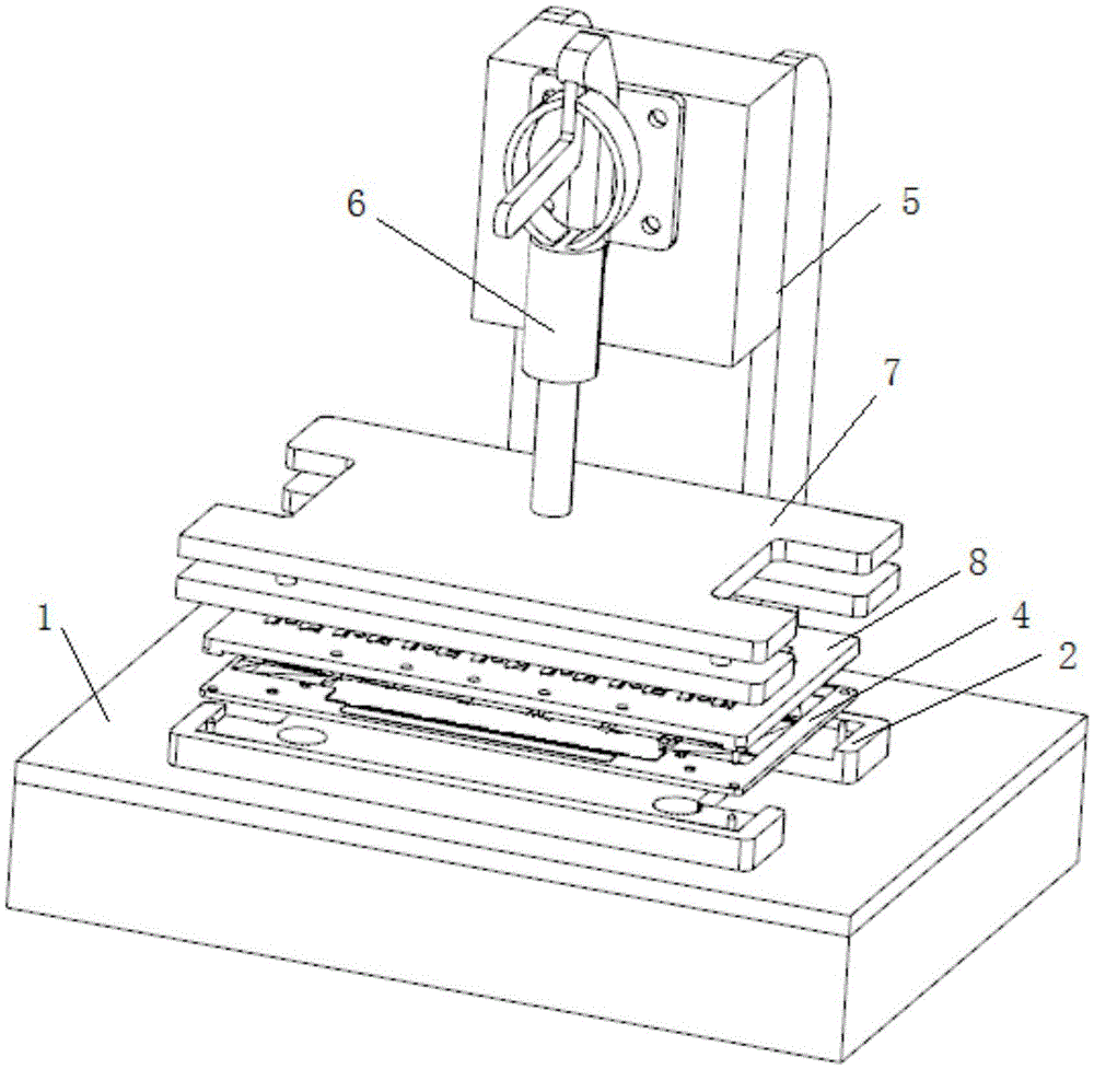
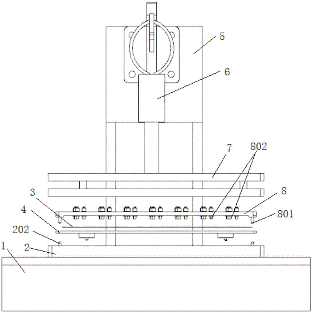
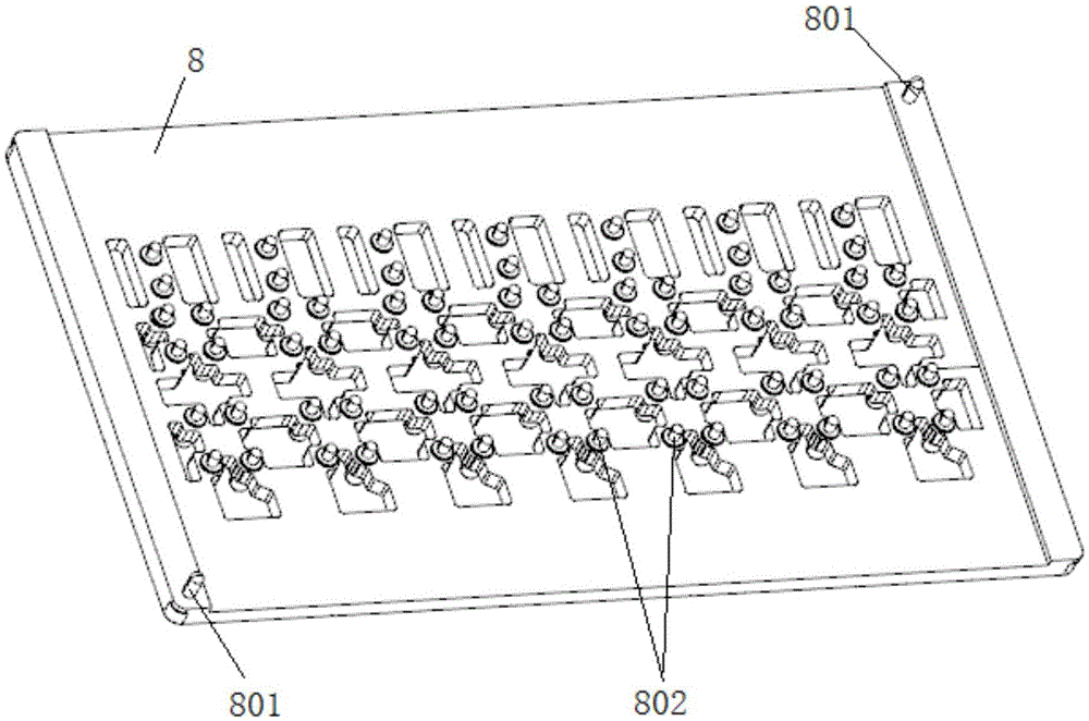
[0032] see Figure 1 to Figure 6 As shown, the present invention provides a magnetic fixture, including an installation platform 1, a positioning base 2 is fixed on the installation platform 1, and at least two first positioning pins 201 are arranged on the positioning base 2, and the positioning base 2 The top of 2 places magnetic steel sheet 3, FPC unreinforced supporting electronic components, and magnetic bottom plate 4 sequentially from top to bottom. hole 401, the first positioning pin 201 extends into the first positioning hole 401, the number of the first positioning hole 401 is greater than the number of the first positioning pin 201, and the magnetic steel sheet 3 is provided with Several through holes 301 for printing solder paste.

[0033] Wherein, at least one reinforcing bar is also fixed on the edge of the positioning base 2. In this embodiment, two reinfor...


PUM


Abstract

The invention discloses a magnetic fixture and an FPC non-reinforce support electronic assembly welding process applying the magnetic fixture. The magnetic fixture comprises an installation platform and a positioning base. A first positioning hole is disposed in the positioning base. A magnetic steel sheet, an FPC non-reinforced support electronic assembly and a magnetic base plate are sequentially placed on the top of the positioning base from top to bottom. A first positioning pin is disposed at the bottom of the magnetic base plate, and the first positioning pin extends into the first positioning hole. According to the magnetic fixture and the process, the positioning base, the magnetic base plate and a spring PIN upper cover plate are positioned by using the first positioning pin, a second positioning pin, and the first positioning hole. The spring PIN upper cove plate can pressurize an FPC welding spot section to make an FPC welding surface smooth and prevent phenomena of a bad air welding float height and a negative offset. A pressurizing apparatus can control a pressure magnitude of the spring PIN upper cover plate to prevent damage to FPC, so as to improve welding quality of a solder joint and production efficiency, and reduce production cost.

Description

technical field [0001] The invention relates to a magnetic jig and a welding process for FPC unreinforced supporting electronic components using the same. Background technique [0002] Usually, the welding process of FPC (flexible circuit board) electronic components without reinforcement and support is completed by means of the traditional method of bottom cover plate or the cover plate made of synthetic stone material after secondary reflow soldering. This method has the following defects : [0003] 1. Using the traditional welding process, it is easy to cause abnormal function of the product after welding, that is, failure to conduct and short circuit; [0004] 2. Poor floating height of empty soldering, because most customers require that there is no need to add add-ons before welding the flexible circuit board, which will lead to uneven bottom of the welding components during welding, resulting in batch empty soldering and poor floating height; [0005] 3. Poor offset...

Claims


Application Information

Patent Timeline
IPC IPC(8): H05K3/34
CPCH05K3/34
Inventor 吴冬平郭跃
Owner 昆山圆裕电子科技有限公司
Learn More