Casting shakeout hopper based on timing forward and reverse rotation control

A forward-reversing, sand-shaking bucket technology, which is applied in the direction of manufacturing tools, casting molding equipment, and cleaning/processing machinery for mold materials, can solve the problems of low sand-shaking efficiency and high labor intensity, and achieve continuous The effect of feeding materials, improving feeding efficiency, reducing labor intensity and labor cost

Inactive Publication Date: 2016-04-13
WUXI XINMAO FORGING CO LTD
9 Cites 0 Cited by

AI-Extracted Technical Summary

Problems solved by technology

The above-mentioned anti-clogging method has high ...

Method used

When the present invention works, motor 7 drives rotating shaft 9 to rotate, and rotating shaft 9 drives material guide cover 4 to rotate, and guide material cover 4 stirs sand material wherein by connecting rod 11, simultaneously, stirring shaft 12 on connecting rod 11 And the agitating plate 13 rotates with the sand material, thereby avoiding the sand material from blocking the di...

Abstract

The invention relates to a casting shakeout hopper based on timing forward and reverse rotation control. The casting shakeout hopper comprises a hopper body, wherein a discharge opening is formed in the lower end of the hopper body; a support sleeve is mounted on the outer side of the discharge opening; a material guiding sleeve is mounted on the inner side of the support sleeve; the material guiding sleeve is rotationally mounted between the lower end of the discharge opening and an inward folded ring of the support sleeve through a thrust bearing; balls are mounted in a circular groove in the upper surface of the inward folded ring; a support seat is mounted on the inner wall of the discharge opening through a plurality of support rods; a motor protection cover and a motor in the motor protection cover are mounted on the lower surface of the support seat; a rotating shaft is mounted on the output shaft of the motor; connecting rods are connected up and down with the side wall of the rotating shaft; mounting sleeves are arranged at end parts of the connecting rods; the mounting sleeves are propped against the inner wall of the material guiding sleeve and are connected with the outer wall of the material guiding sleeve through screws; stirring shafts are rotationally mounted on the outer walls of the connecting rods and are arranged upwards; stirring blades are spirally connected with the outer walls of the stirring shafts; a control box is mounted on the outer side of the support sleeve; and a timing controller and a forward and reverse rotation controller of the motor are mounted in the control box.

Application Domain

Technology Topic

Image

  • Casting shakeout hopper based on timing forward and reverse rotation control

Examples

  • Experimental program(1)

Example Embodiment

[0010] The specific embodiments of the present invention will be further described below in conjunction with the accompanying drawings.
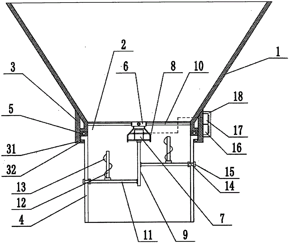
[0011] Such as figure 1 As shown, the sand falling hopper for casting based on timing forward and reverse control of this embodiment includes a hopper body 1. The lower end of the hopper body 1 is provided with a discharge port 2, and a support sleeve 3 is installed outside the discharge port 2 to support A guide sleeve 4 is installed on the inner side of the sleeve 3. The guide sleeve 4 is rotatably installed between the lower end of the discharge port 2 and the inner folding ring 31 of the support sleeve 3 through a thrust bearing 5, in the ring groove on the upper surface of the inner folding ring 31 Balls 32 are installed; the inner wall of the discharge port 2 is equipped with a support base 6 through multiple support rods 10. The lower surface of the support base 6 is mounted with a motor protection cover 8 and a motor 7 located in the motor protection cover 8. The output of the motor 7 A rotating shaft 9 is installed on the shaft. The side wall of the rotating shaft 9 is connected with a connecting rod 11 up and down. The end of the connecting rod 11 is provided with a mounting sleeve 14. The mounting sleeve 14 abuts against the inner wall of the guide sleeve 4 and contacts the outer wall of the guide sleeve 4 The screw 15 is screwed; the outer wall of the connecting rod 11 is rotated and installed with a stirring shaft 12, the stirring shaft 12 is arranged upward, and the outer wall is spirally connected with the stirring sheet 13; the outer side of the support sleeve 3 is installed with a control box 18, which is installed in the control box 18 There are a timing controller 16 and a forward and reverse controller 17 of the motor 7.
[0012] When the present invention is working, the motor 7 drives the rotating shaft 9 to rotate, and the rotating shaft 9 drives the guide sleeve 4 to rotate. The guide sleeve 4 agitates the sand in it through the connecting rod 11. At the same time, the agitating shaft 12 and the agitating plate on the connecting rod 11 13 Follow the rotation of the sand material to avoid the sand material from blocking the discharge port 2 and ensure the continuous supply of sand material; the timing controller 16 in the control box 18 sets the time, and the forward and reverse controller 17 regularly controls the forward direction of the motor 7 Rotation and reversal, so as to control the forward and reverse rotation of the guide sleeve 4 and the connecting rod 11, and further ensure that the discharge port 2 is not blocked.
[0013] The above-mentioned embodiments are the preferred embodiments of the present invention. They are only used to facilitate the description of the present invention, and are not intended to limit the present invention in any form. Anyone with ordinary knowledge in the technical field, if they do not deviate from the provisions of the present invention Within the scope of the technical features, the equivalent embodiments with partial changes or modifications made using the technical content disclosed in the present invention without departing from the technical features of the present invention still fall within the scope of the technical features of the present invention.

PUM

no PUM

Description & Claims & Application Information

We can also present the details of the Description, Claims and Application information to help users get a comprehensive understanding of the technical details of the patent, such as background art, summary of invention, brief description of drawings, description of embodiments, and other original content. On the other hand, users can also determine the specific scope of protection of the technology through the list of claims; as well as understand the changes in the life cycle of the technology with the presentation of the patent timeline. Login to view more.

Similar technology patents

Anti-blocking shakeout hopper for dry-sand full mold casting

InactiveCN105382184AAvoid cloggingGuaranteed continuous supplyMould handling/dressing devicesFull-mold castingDischarge efficiency
Owner:WUXI XINMAO FORGING CO LTD

Efficient-guiding type casting shakeout hopper

InactiveCN105382189AAvoid cloggingGuaranteed continuous supplyMould handling/dressing devicesArchitectural engineering
Owner:WUXI XINMAO FORGING CO LTD

New energy power supply system

ActiveCN114865780AGuaranteed continuous supplyAvoid power outageVehicular energy storageInformation technology support systemPower storagePower grid
Owner:FOSHAN POWER SUPPLY BUREAU GUANGDONG POWER GRID +1

Classification and recommendation of technical efficacy words

  • Improve feeding efficiency
  • Guaranteed continuous supply

Feeding device for medical accessories

InactiveCN105173627ASpace-saving layoutImprove feeding efficiencyConveyor partsMedical instruments
Owner:MAIDER MEDICAL IND EQUIP

Three-rail vibrating plate

Owner:ACME ELECTRONICS KUNSHAN

Automatic feeding device

ActiveCN104058243ASolve the problem of automatic feedingImprove feeding efficiencyConveyor partsManipulatorEngineering
Owner:SUZHOU LING AUTOMATION EQUIP

Continuous fixed quantity discharging device and material blending system using the same

InactiveCN1977151AContinuous dischargeGuaranteed continuous supplyFlow mixersMixer accessoriesMaterial storageMixing ratio
Owner:MATSUI MFG

Liquid distribution device

ActiveUS20150153746A1Guaranteed continuous supplyAutomatic controlControl using interconnected flow control elementsDispersed particle separationConstant rateEngineering
Owner:AMTPACIFIC

Cultivation box for agricultural seedling

ActiveCN111512851AAvoid tipping and falling situationsGuaranteed continuous supplyClimate change adaptationGreenhouse cultivationAgricultural engineeringAgriculture
Owner:新格林(浙江)生态科技有限公司
Why Eureka
Try Eureka