Device for cooling hot node and mould

A node and mold technology, which is applied in the field of cooling hot node devices and molds, can solve the problems of poor cooling device effect and inconvenient disassembly and assembly, and achieve the effects of convenient disassembly, good cooling effect, and increased residence time

Inactive Publication Date: 2016-04-13
TIANJIN AITIAN AUTO PARTS
View PDF9 Cites 11 Cited by
  • Summary
  • Abstract
  • Description
  • Claims
  • Application Information

AI Technical Summary

Problems solved by technology

[0003] In view of this, the present invention aims to propose a device and mold for cooling hot nodes, so as to

Method used


Image

  • Device for cooling hot node and mould
  • Device for cooling hot node and mould
  • Device for cooling hot node and mould

Examples


Example Embodiment

[0021] It should be noted that the embodiments of the present invention and the features in the embodiments can be combined with each other if there is no conflict.

[0022] In the description of the present invention, it should be understood that the terms "center", "longitudinal", "transverse", "upper", "lower", "front", "rear", "left", "right", " The orientation or positional relationship indicated by "vertical", "horizontal", "top", "bottom", "inner", "outer" etc. is based on the orientation or positional relationship shown in the drawings, and is only for the convenience of describing the present invention and The description is simplified, rather than indicating or implying that the pointed device or element must have a specific orientation, be constructed and operated in a specific orientation, and therefore cannot be understood as a limitation of the present invention. In addition, the terms "first", "second", etc. are only used for descriptive purposes, and cannot be und...


PUM

PropertyMeasurementUnit
Wall thicknessaaaaaaaaaa

Abstract

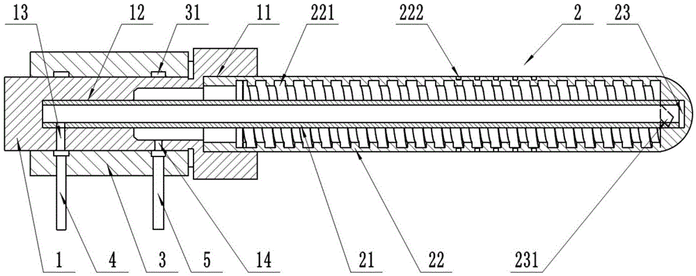
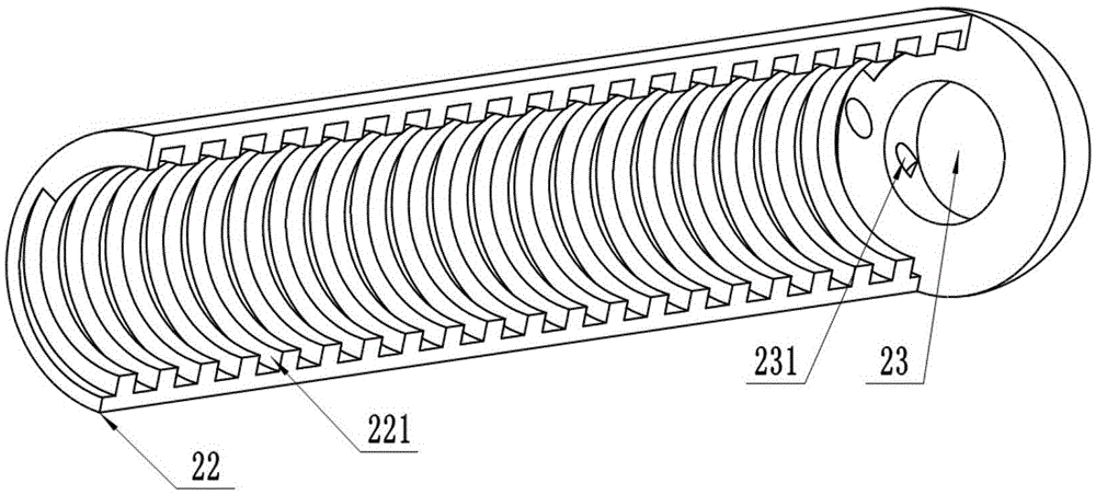
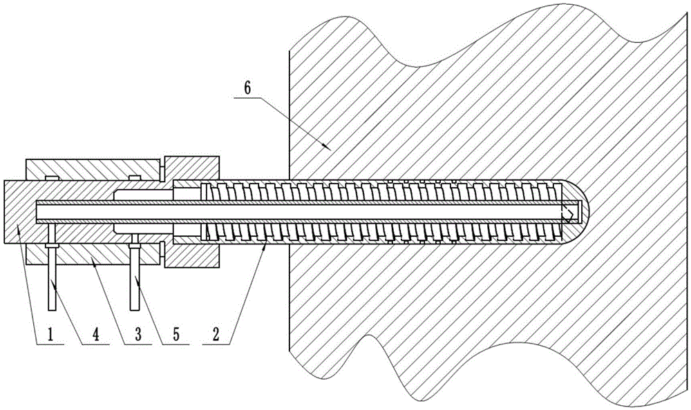
The invention provides a device for cooling a hot node and a mould. The device comprises a connector part and a cooling part, wherein the connector part and the cooling part are connected with each other. The cooling part comprises an inner pipe and an outer pipe, wherein the inner pipe and the outer pipe are concentrically arranged. One end of the outer pipe is connected with the connector part, the other end of the outer pipe is closed, and a spiral water channel is formed in the inner wall of the outer pipe. A blind hole is formed inside the closed end of the outer pipe, and the blind hole and the spiral water channel are communicated through a connecting channel. One end of the inner pipe is fixedly connected with the connector part, and the other end of the inner pipe is located in the blind hole. A threaded hole is formed in one end of the connector part, threads are formed in the outer side of one end of the outer pipe, a mounting hole is formed in the bottom of the threaded hole, and the inner pipe is located in the mounting hole. A water inlet hole and a water outlet hole are further formed in the connector part, the water inlet hole is communicated with the mounting hole and the inner pipe, and the water outlet hole is communicated with the threaded hole. By the adoption of the scheme, due to the fact that the spiral water channel is formed in the inner wall of the outer pipe, the staying time of cooling water is prolonged, the area where the cooling water flows through is enlarged, the cooling effect is good, and the product quality is high; and due to the fact that direct insertion type mounting is adopted, disassembly and assembly are convenient, and the working efficiency is improved.

Description

technical field [0001] The invention belongs to the field of die-casting production, in particular to a device and mold for cooling hot nodes. Background technique [0002] Mold temperature is an important factor affecting the quality of die castings, but it is often not strictly controlled in the production process. Most die castings with simple shapes and good die casting process do not require high mold temperature control, and the mold temperature is within a wide range. Qualified die castings can still be produced when changing. In the continuous mass production of large and medium-sized castings or thick-walled castings, the solidification time of the metal in the molten state at each point in the cavity is not equal, which will cause thermal stress in the casting after solidification, resulting in deformation, cracks, Defects such as shrinkage porosity, shrinkage cavity, cold shut, and pores are to maintain the thermal balance of the mold. At this time, use more wat...

Claims


Application Information

Patent Timeline
IPC IPC(8): B22D17/22
CPCB22D17/2218
Inventor 袁茂凯
Owner TIANJIN AITIAN AUTO PARTS
Why Eureka
Try Eureka