Automatic conducting strip sticking, welding and bending equipment and machining technology thereof

An automatic patch, conductive sheet technology, applied in other manufacturing equipment/tools, manufacturing tools, etc., can solve the problems of conductive sheet falling off, difficult to control, slow manual operation, etc.

Inactive Publication Date: 2016-04-13
NANJING ZHENGUAN ELECTRONICS TECH CO LTD
View PDF8 Cites 11 Cited by
  • Summary
  • Abstract
  • Description
  • Claims
  • Application Information

AI Technical Summary

Problems solved by technology

During the bending process, due to the uneven force used each time, the bending angle of each completed conductive sheet will be different; moreover, because the manual op

Method used


Image

  • Automatic conducting strip sticking, welding and bending equipment and machining technology thereof
  • Automatic conducting strip sticking, welding and bending equipment and machining technology thereof
  • Automatic conducting strip sticking, welding and bending equipment and machining technology thereof

Examples


Embodiment 1

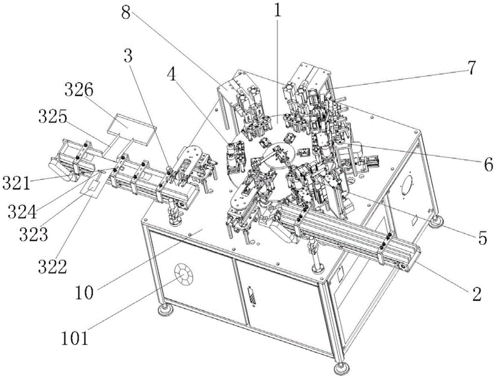
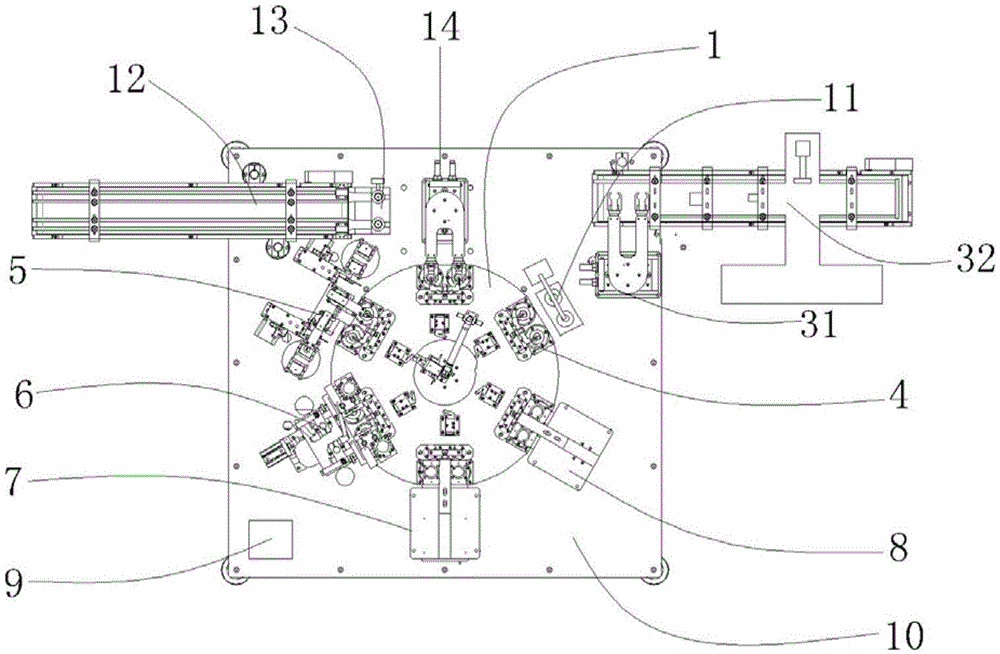
[0043] Such as Figure 1-9 As shown, the automatic patch welding and bending equipment for conductive sheets includes a workbench on which a turntable 1, a feeding device 2 and a discharging device 3 are installed, and the feeding device 2 includes a clamping device 14, a conveyor belt 1 12. The end of the conveyor belt 12 is provided with a tray 13; the discharge device 3 includes a clamping device 2 31 and a conveyor belt 2 32, and the middle part of the conveyor belt 2 32 is provided with a good product detector 321, and the good product detector After 321, a support frame 322 is also installed on one side of the conveyor belt 2 32, and a push cylinder 323 is installed on the support frame 322, and a push rod 324 is provided on the push cylinder 323, and the good product detector 321 is connected with the The above-described push cylinder 323 is electrically linked; the other side of the conveyor belt 2 32 is also provided with a slope 325, and the outlet end of the slope 3...

Embodiment 2

[0061] Such as Figure 1-9 As shown, the automatic patch welding and bending equipment for conductive sheets includes a workbench on which a turntable 1, a feeding device 2 and a discharging device 3 are installed, and the feeding device 2 includes a clamping device 14, a conveyor belt 1 12. The end of the conveyor belt 12 is provided with a tray 13; the discharge device 3 includes a clamping device 2 31 and a conveyor belt 2 32, and the middle part of the conveyor belt 2 32 is provided with a good product detector 321, and the good product detector After 321, a support frame 322 is also installed on one side of the conveyor belt 2 32, and a push cylinder 323 is installed on the support frame 322, and a push rod 324 is provided on the push cylinder 323, and the good product detector 321 is connected with the The above-described push cylinder 323 is electrically linked; the other side of the conveyor belt 2 32 is also provided with a slope 325, and the outlet end of the slope 3...

Embodiment 3

[0078] Such as Figure 1-10 As shown, the automatic patch welding and bending equipment for conductive sheets includes a workbench on which a turntable 1, a feeding device 2 and a discharging device 3 are installed, and the feeding device 2 includes a clamping device 14, a conveyor belt 1 12. The end of the conveyor belt 12 is provided with a tray 13; the discharge device 3 includes a clamping device 2 31 and a conveyor belt 32, and the front part of the conveyor belt 2 32 is provided with a deburring structure 327, and the deburring The structure 327 is pressed down by the lifting cylinder 328 to flatten the burrs on the solder of the conductive sheet; the middle part of the conveyor belt 2 32 is also provided with a good product detector 321, and the good product detector 321 is also installed on one side of the conveyor belt 2 32 There is a support frame 322, a push cylinder 323 is installed on the support frame 322, a push rod 324 is arranged on the push cylinder 323, and ...


PUM


Abstract

The invention relates to electronic product manufacturing technology equipment, and particularly provides automatic conducting strip sticking, welding and bending equipment and a machining technology thereof. The equipment comprises a workbench, and the workbench is provided with a rotary plate, a feeding device and a discharging device. The automatic sticking, welding and bending equipment is characterized in that the rotary plate is provided with a gripping device and sequentially provided with a strip feeding device, a welding device, a first bending device and a second bending device along the edge. By adopting the equipment, automatic conducting strip sticking, welding and bending can be achieved, and integrated production of welding and bending can be achieved by arranging the welding device, the first bending device and the second bending device on the workbench; meanwhile, through cooperation of the first bending device and the second bending device, a conducting strip can be stressed uniformly in the bending process, and the fall-off phenomenon cannot occur.

Description

technical field [0001] The invention relates to an electronic product preparation process equipment, in particular to an automatic patch welding and bending equipment for a conductive sheet and a processing technique thereof. Background technique [0002] The production process of the traditional conductive sheet is welding first, and then manual bending. During the bending process, due to the uneven force used each time, the bending angle of each completed conductive sheet will be different; moreover, because the manual operation is not easy to control, the previously welded conductive sheet is prone to fall off. At the same time, the manual operation is slow and the production volume is small. [0003] For example, CN203356805U discloses a conductive sheet automatic patch welding device, including a feed system, a pretreatment system, a patch system, and a post-processing system, feeding through the feed system, and then going through pretreatment and patch processes resp...

Claims


Application Information

Patent Timeline
IPC IPC(8): B23P23/00
CPCB23P23/00
Inventor 杨金芝
Owner NANJING ZHENGUAN ELECTRONICS TECH CO LTD
Why Eureka
Try Eureka