Eureka AIR delivers breakthrough ideas for toughest innovation challenges, trusted by R&D personnel around the world.

Novel wheel tread structure of high-speed motor train unit

A high-speed EMU and wheel tread technology, which is applied in the direction of wheels, wheels characterized by track running parts, vehicle parts, etc., can solve the problem that the shape of the wheel tread cannot be matched at the same time, the dynamic performance of the train is balanced and balanced, and the repair period cannot be repaired. Improve and other problems to achieve the effect of increasing the adaptability of vehicle suspension parameters, alleviating abnormal vehicle vibration, and improving the matching relationship between wheel and rail

Active Publication Date: 2016-04-13
CRRC CHANGCHUN RAILWAY VEHICLES CO LTD +2
View PDF5 Cites 6 Cited by
  • Summary
  • Abstract
  • Description
  • Claims
  • Application Information

AI Technical Summary

Problems solved by technology

[0004] In order to solve the problem that the wheel tread shapes of old models such as the existing domestic EMU S1002CN cannot match the old CH60 rail profile and the new 60N rail profile at the same time, and the wheel tread shapes of the existing old models cannot The technical problem of achieving the best consideration and balance in the two aspects of improving the turnaround cycle and improving the dynamic performance of the train at the same time, the invention provides a new wheel tread structure for high-speed EMUs

Method used


Image

  • Novel wheel tread structure of high-speed motor train unit
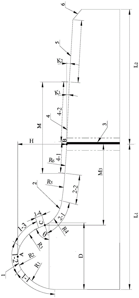
  • Novel wheel tread structure of high-speed motor train unit

Examples


Embodiment Construction

[0021] The present invention will be described in further detail below in conjunction with the accompanying drawings.

[0022] like figure 1 As shown, the new wheel tread structure of the high-speed EMU of the present invention includes a wheel rim 1, a throat root circle height taper area 2, a rolling circle 3, a normal working area 4, an outer end low taper area 5 and an outer end face chamfer area 6, It is characterized in that: the rim 1 includes the end face 1-1 of the first arc segment of the rim, the end face 1-2 of the second arc segment of the rim, the end face 1-3 of the third arc segment of the rim and the end face 1 of the straight segment of the rim -4, they are all smoothly connected in a tangent form sequentially. Throat root circular height taper zone 2 includes the end face 2-1 of the first circular arc segment in the throat root circular height taper zone and the end face 2-2 of the second circular arc segment in the throat root circular height taper zone, t...


PUM


Abstract

The invention relates to a novel wheel tread structure for a high-speed motor train unit, and belongs to the field of railway vehicle wheel tread structures. The wheel tread structure can be completely matched with and completely adapt to the profile of CN60 novel railways, and a small curvature radius of a first arc segment end surface of a throat root circle high taper region is adopted to avoid the destabilization of train wheels produced by that the equivalent taper of a tread is too high, and avoid the rocking of motor trains caused by that the equivalent taper of the tread is too low. A normal operating region cooperates with a low taper region at the outer side of an end part of the tread to have the effect of enlarging the contacting area of the tread and the railways, and the wheels can be allowed to bear a higher axle weight load under the same contact stress. According to the novel wheel tread structure disclosed by the invention, the purposes that the tread wear is retarded and the wheel rotating period is prolonged are achieved through optimizing the optimal position of a rolling circle, and the adaptability of the tread structure to the change of a steel rail profile is greatly improved through the given parameter settings which are calculated and preferred, and the purpose of obtaining the ideal effects of concurrently considering and balancing two aspects of restraining snaking motion and prolonging the wheel rotating period is achieved.

Description

technical field [0001] The invention belongs to the field of wheel tread structures of rail vehicles, and in particular relates to a novel wheel tread structure of high-speed EMUs. Background technique [0002] like figure 1 As shown, the tread structure of the wheel of the rail passenger car is the contour line formed by the rim and the tread M on the radial section of the wheel, and the tread structure generally includes a wheel rim 1, a throat root circular height taper according to a well-known definition method in the art Area 2, rolling circle 3, normal working area 4, outer end low taper 5 and outer end face chamfering area 6 and other main structures, their outer contour lines are connected in sequence to form the overall tread structure contour curve. Among them, the rolling circle 3 is defined as the position of point B at a distance of L1=70mm from the inner surface of the tread rim, and the vertical diameter of the rolling circle 3 is used as the dividing line, ...

Claims


Application Information

Patent Timeline
Patent Type & Authority Applications(China)
IPC IPC(8): B60B17/00
CPCB60B17/0082
Inventor 宋春元齐延辉李福梁志超刘志泰梁树林李国栋池茂儒沈文林邬平波黄彩虹李永恒
Owner CRRC CHANGCHUN RAILWAY VEHICLES CO LTD
Why Eureka
Eureka Blog
Learn More