
Independent suspension front axle with virtual kingpin structure
A technology of independent suspension and virtual kingpin, applied in the field of auto parts, can solve the problems of complex support arm structure, high processing requirements, high assembly cost, etc., achieve good driving comfort and handling stability, and small changes in tire motion parameters , the effect of good handling stability
- Summary
- Abstract
- Description
- Claims
- Application Information
AI Technical Summary
Problems solved by technology
Method used
Image

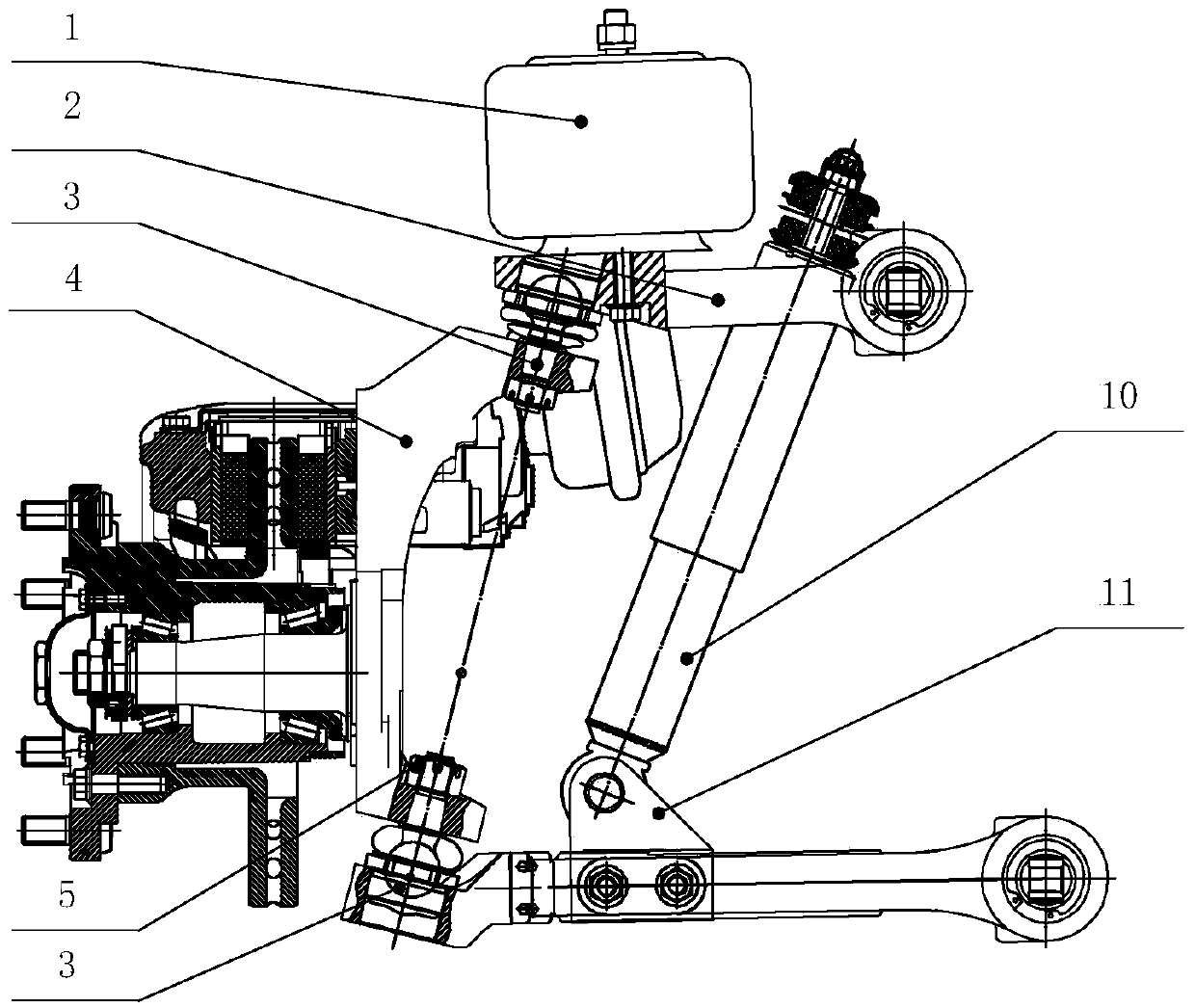
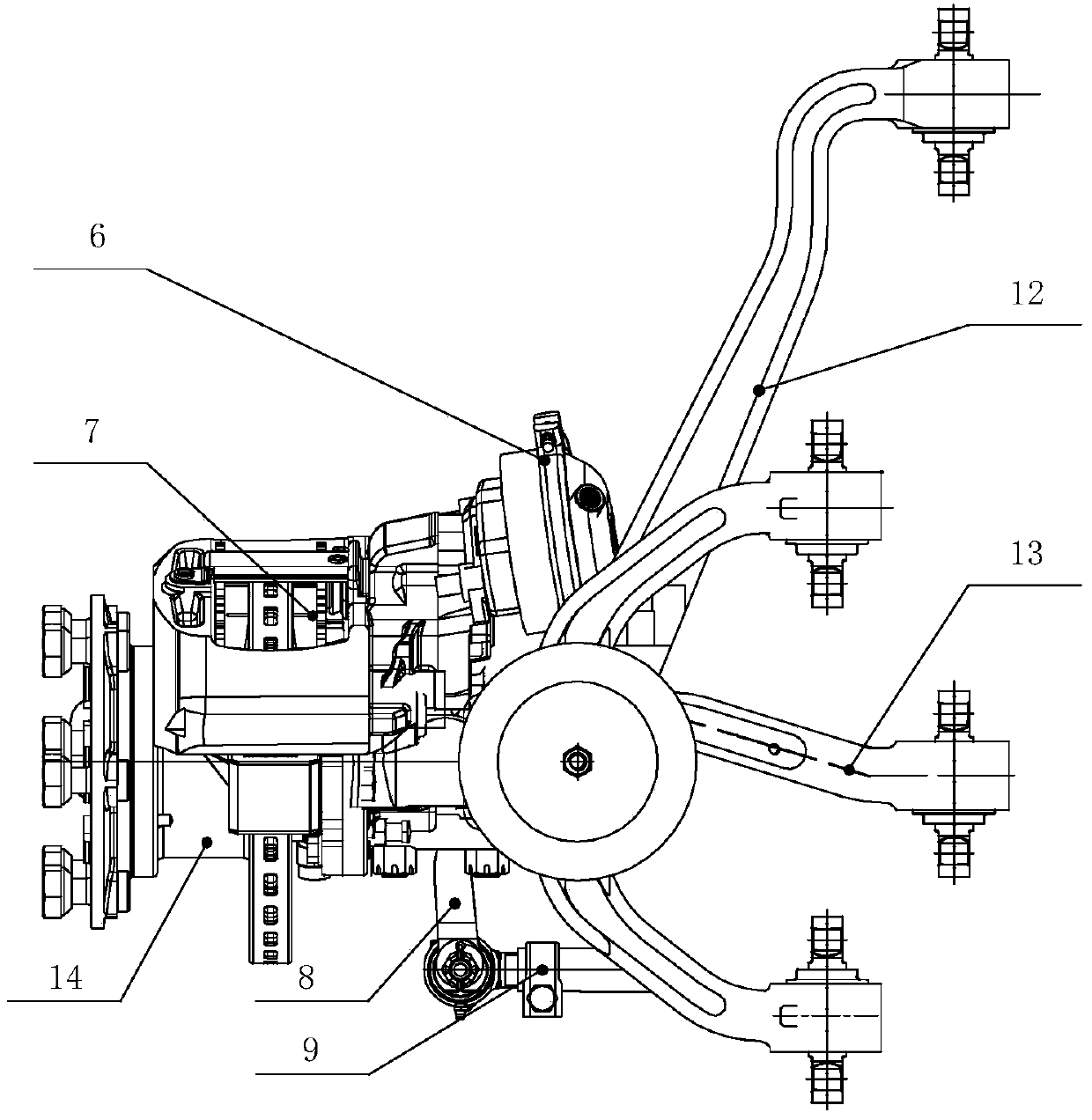
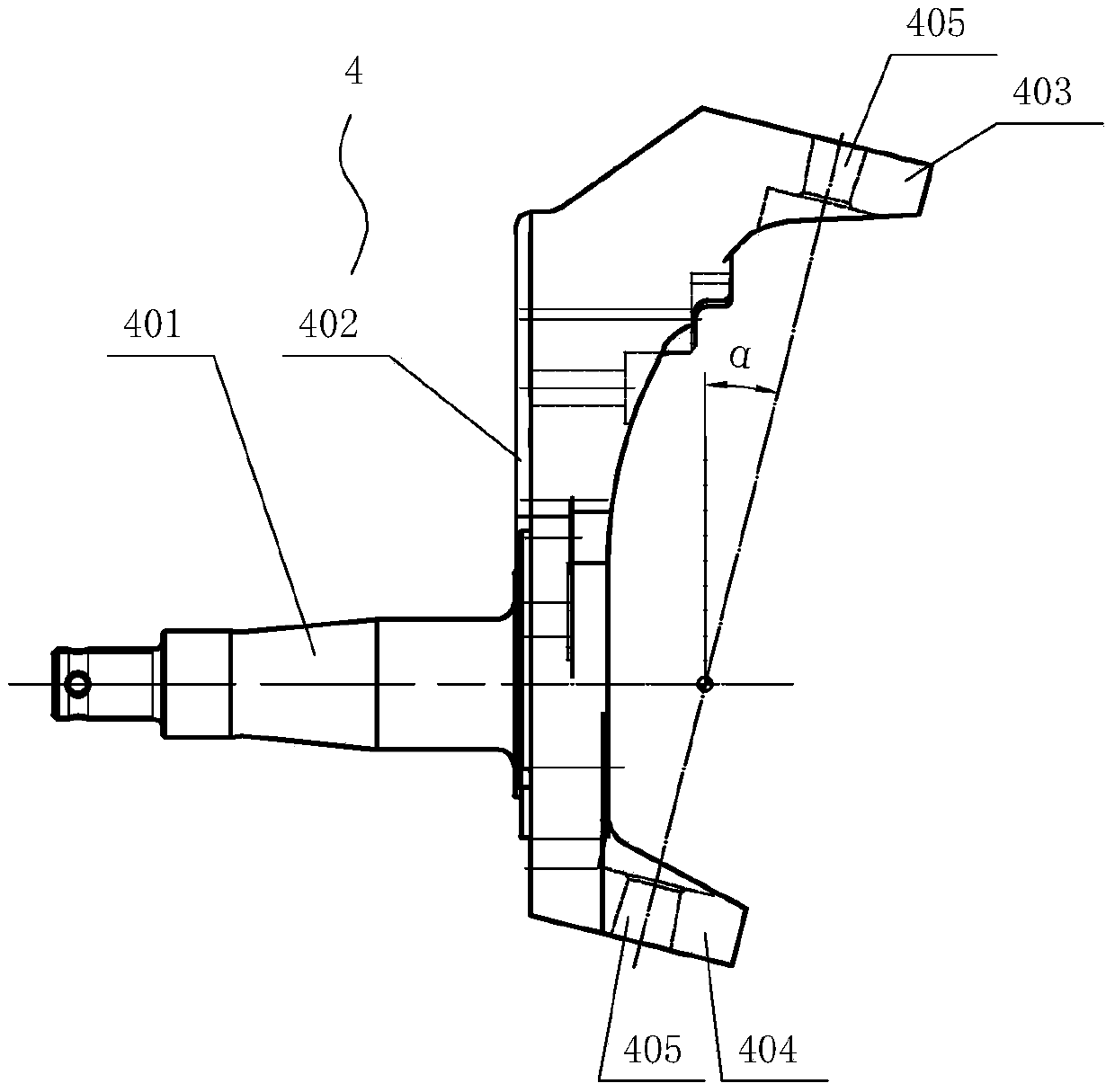
Examples
Embodiment 1
[0066] An independent suspension front axle with a virtual kingpin structure, including an airbag assembly 1, an upper swing arm 2, a suspension ball joint assembly 3, a steering knuckle 4, an air chamber assembly 6, a brake assembly 7, and a tie rod Arm 8, tie rod 9, shock absorber assembly 10, lower swing arm, wheel hub and brake disc assembly 14;
[0067] The airbag assembly 1 is directly installed on the upper swing arm 2, the upper end of the upper swing arm 2 and the steering knuckle 4 are connected by a suspension ball joint assembly 3, and the lower end of the steering knuckle 4 is connected by a suspension ball joint assembly 3 is connected with the lower swing arm, and the steering knuckle 4 is also respectively connected with the brake assembly 7, the wheel hub and the brake disc assembly 14; the air chamber assembly 6 is installed on the brake assembly 7, and the tie rod 9 passes through the tie rod The arm 8 is connected with the steering knuckle, and the shock ab...
PUM
 Abstract
Description
Claims
Application Information