Photobioreactor system used for air purification

A photobioreactor and reactor technology, applied in the field of air purification, can solve problems such as affecting the carbon dioxide removal performance of the photobioreactor

Inactive Publication Date: 2016-04-13
NANO & ADVANCED MATERIALS INST
View PDF5 Cites 3 Cited by
  • Summary
  • Abstract
  • Description
  • Claims
  • Application Information

AI Technical Summary

Problems solved by technology

[0006] However, the local climate can affect t...

Method used


Image

  • Photobioreactor system used for air purification
  • Photobioreactor system used for air purification
  • Photobioreactor system used for air purification

Examples


example 1

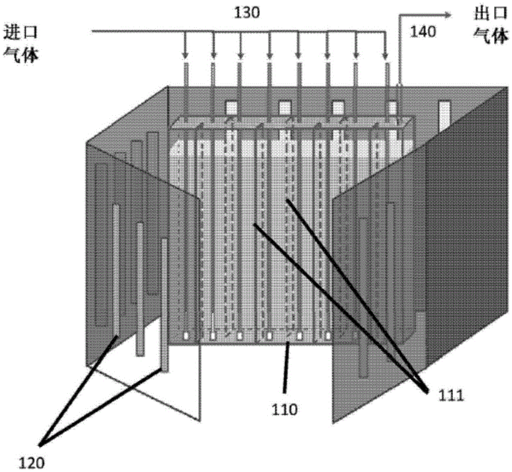
[0044] implement figure 1 An embodiment of the invention is shown to purify CO 2 polluted air. The reactor is a plate reactor with a single partition. The capacity of the reactor is 4L. The reactor works indoors. The initial concentration of Chlorella sp in the modified BBM was 1,200,000 microalgal cells / ml matrix. The temperature of the reactor tank was 30°C. The continuous light intensity of the LED device is 400μmol / m 2 the s -1 .The working cycle is two weeks. Inlet CO 2 The concentration is 490ppm, and the flow rate is 1000ml / min. After 24 hours, the CO at the outlet 2 The concentration was measured at 146ppm, consuming 70% of the CO 2 . The reactor can maintain more than 70% CO over a two-week duty cycle 2 consumption. Figure 4 The graph in shows the CO over a two-week working period 2 consumption performance.

example 2

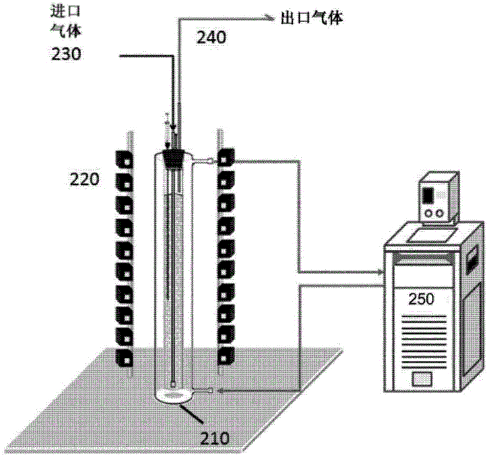
[0046] implement figure 2 The embodiment of the invention shown to purify CO 2 polluted air. The reactor is a tubular reactor with a capacity of 1000ml. The ratio of diameter to height of the reactor is 1:10. The reactor works indoors. The initial concentration of Chlorella in the modified BBM was 1,200,000 microalgal cells / ml matrix. The temperature of the reaction tank was 30°C. The continuous light intensity of the LED device is 400μmol / m 2 the s -1 . CO at the inlet 2 The concentration is 450ppm, and the flow rate is 1000ml / min. After 24 hours, the gas outlet CO 2 Concentration measured at 90ppm, consumes more than 80% of CO 2 . The reactor can maintain more than 80% CO during 250 hours of operation 2 consumption. Figure 5 The curve in shows the CO over a two-week working period 2 consumption performance.

example 3

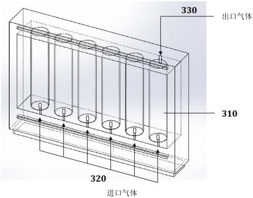
[0048] implement image 3 The embodiment of the invention shown to purify CO 2 polluted air. The reactor is a tubular reactor with a capacity of 100 L. The diameter and height ratio of the reactor is 1:5. Six reactors are placed in a row. The reactor was placed to work outdoors. The initial concentration of Chlorella in the modified BBM was 1,200,000 microalgal cells / ml matrix. Sunlight provides natural light to the medium. Inlet CO 2 The concentration is 400ppm, and the flow rate is 10L / min. After 72 hours, the CO at the outlet 2 Concentration measured at 45ppm, over 80% CO consumed 2 . The reactor can maintain more than 80% CO over an operating period of 18 days 2 Consumption, during a 30-day working period, can maintain 40% CO 2 consumption. Figure 6 The curve in shows the CO over a month of work 2 consumption performance.


PUM


Abstract

The invention relates to a photobioreactor system used for air purification used for air purification. The invention provides a system used for reducing the concentration of carbon dioxide in air in regions with subtropical to temperate climates and a method for using the system to reduce the concentration of carbon dioxide.

Description

[0001] Cross References to Related Applications [0002] Pursuant to 35 U.S.C § 119(e), this application is called upon for application No. 62 / 124,348, filed December 16, 2014, entitled "Design of a Microalgae Photobioreactor for Cleaning Indoor and Outdoor Hong Kong Air" The non-provisional patent application to which the U.S. Provisional Patent Application is entitled, the disclosure of the U.S. Provisional Patent Application is hereby incorporated by reference in its entirety. technical field [0003] The present invention relates to air purification. In particular, the present invention relates to a system for reducing the concentration of carbon dioxide in the air using photosynthetic microalgae in fresh water or sea. The invention is especially suitable for subtropical and temperate climate regions with an average temperature of 15°C to 30°C. Background technique [0004] Emissions of greenhouse gases from vehicles and industries are one of the main contributors to g...

Claims


Application Information

Patent Timeline
IPC IPC(8): C12M1/38C12M1/36C12M1/34C12M1/04C12R1/89
CPCC12M29/00C12M29/06C12M41/06C12M41/26C12M41/34C12M41/40Y02P20/59Y02A50/20
Inventor 刘若天姜乐恒卢轼浚乔纳森·克里斯蒂安图
Owner NANO & ADVANCED MATERIALS INST
Why Eureka
Try Eureka