Photobioreactor system for air purification

a photobioreactor and air purification technology, applied in the field of air purification, can solve problems affecting the performance of the photobioreactor, and achieve the effect of high-efficiency removal of carbon dioxid

Inactive Publication Date: 2015-04-16
NANO & ADVANCED MATERIALS INST
View PDF1 Cites 1 Cited by
  • Summary
  • Abstract
  • Description
  • Claims
  • Application Information

AI Technical Summary

Benefits of technology

[0027]Unlike any existing bioreactor, the present photobioreactor system and method of air purification using the same are adapted to sub-tropical to temperate climates for high efficient removal of carbon dioxide.

Problems solved by technology

However, local climate affects performance of the photobioreactor in removing carbon dioxide.

Method used


Image

  • Photobioreactor system for air purification
  • Photobioreactor system for air purification
  • Photobioreactor system for air purification

Examples


example 1

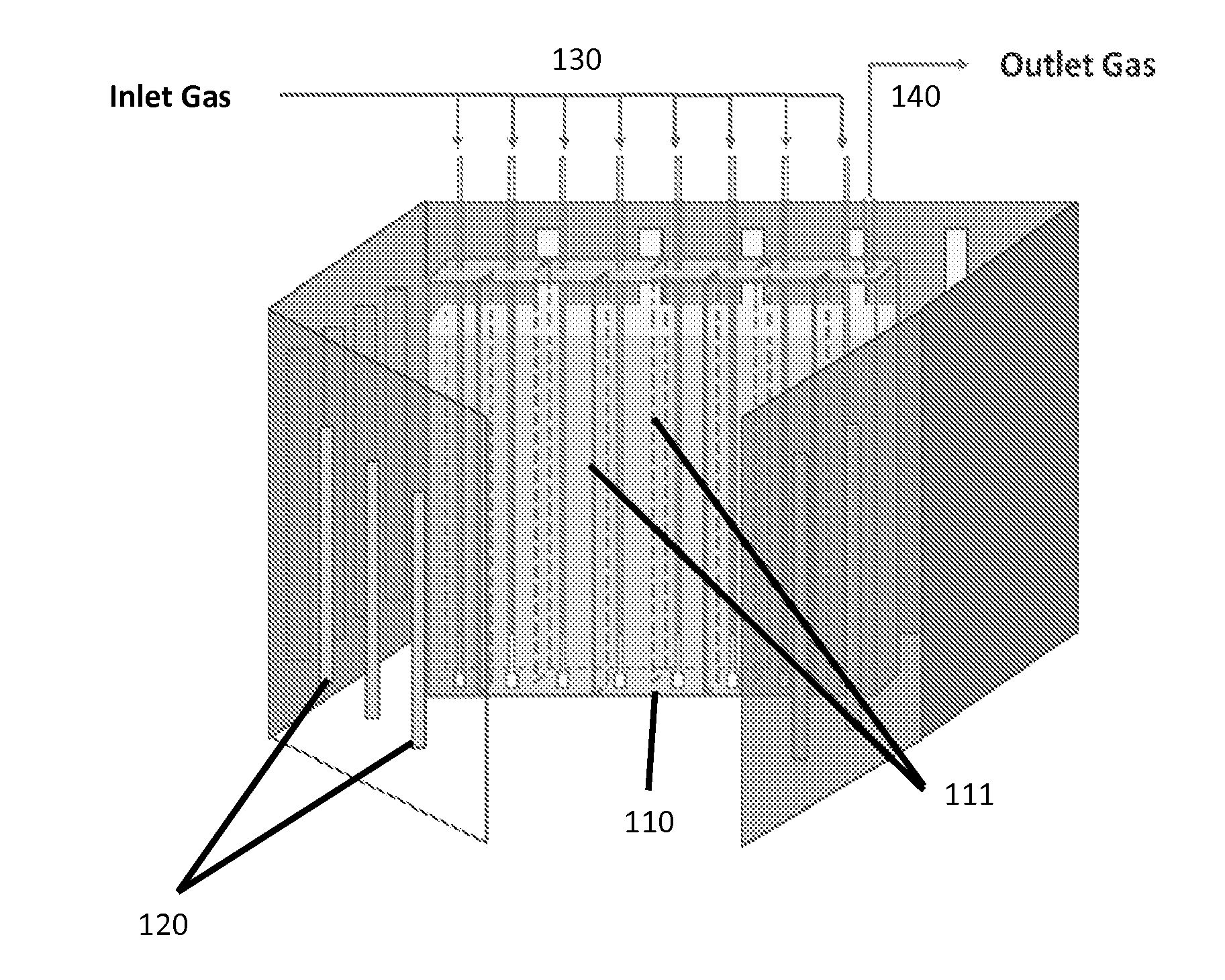
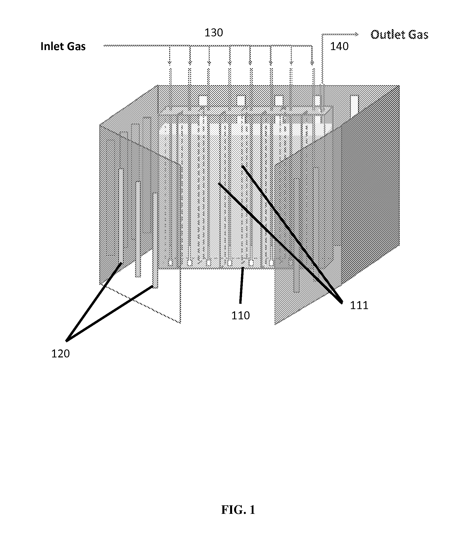
[0051]Purification of CO2 polluted air using the present invention as shown in FIG. 1 is carried out. Chlorella sp. in modified Bold's Basal medium is maintained at 1,200,000 cells of microalgae / mL medium. The temperature of the reactor tank is 25° C. A LED setup radiates light at 200 μmol / m2s−1. The CO2 concentration of the inlet gas is 11.5% and its flow rate is 600 mL / min. After 24 hours, the concentration of the CO2 in the outlet gas is measured to be 3.5%.

example 2

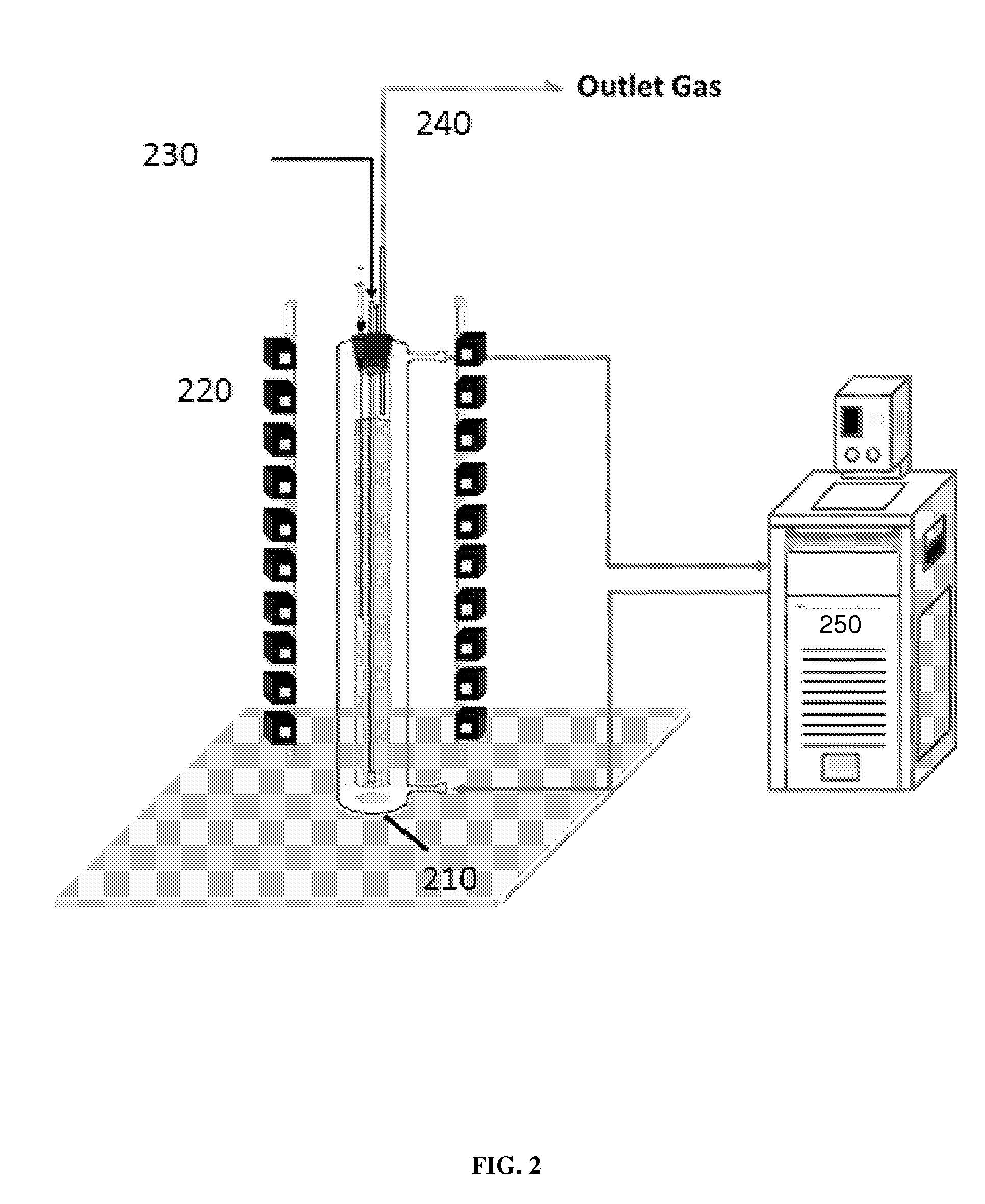
[0052]Purification of CO2 polluted air using the present invention as shown in FIG. 2 is carried out. Chlorella sp. in modified Bold's Basal medium is maintained at 1,200,000 cells of microalgae / mL medium. The temperature of the reactor tank is 20° C. A LED setup radiates light at 80 μmol / m2m−1. The CO2 concentration of the inlet gas is 500 ppm and its flow rate is 350 mL / min. After 5 days, the concentration of the CO2 in the outlet gas is measured to be 130 ppm.

example 3

[0053]The effects of temperature and light intensity on growth rate of the Chlorella species are investigated. The specific growth rate of Chlorella species at different light intensities expressed as photosynthetic photon flux density (PPFD) at 20° C. and 7.5% v / v carbon dioxide concentration is measured (FIG. 3A). It is shown that growth of Chlorella species increases with increase of light intensity up to approximately 450 μmolm−2s−1. The growth of Chlorella species decreases abruptly at light intensity above 450 μmolm−2s−1. The specific growth rate of Chlorella species at different temperatures under constant 7.5% v / v of carbon dioxide concentration and at light intensity of 105 μmolm−2s−1 is then studied. As seen in FIG. 3B, Chlorella growth is higher at a higher temperature up to 35° C., after that it decreases sharply at temperature higher than 35° C. These results show that the temperature and light intensity ranges required in the present photobioreactor system promotes opt...


PUM

PropertyMeasurementUnit
temperatureaaaaaaaaaa
flow rateaaaaaaaaaa
temperatureaaaaaaaaaa

Abstract

The present invention relates to air purification. The present invention provides a system for reducing carbon dioxide concentration in air in locations with sub-tropical to temperate climates and method of reducing carbon dioxide concentration using the system.

Description

CROSS REFERENCE TO RELATED APPLICATION[0001]Pursuant to 35 U.S.C. §119(e), this is a non-provisional patent application claiming benefit from U.S. provisional patent application Ser. No. 61 / 961,447 filed Oct. 15, 2013, and the disclosure of which is incorporated herein by reference in its entirety.FIELD OF THE INVENTION[0002]The present invention relates to air purification. In particular, the present invention relates to a system for reducing carbon dioxide concentration in air using photosynthetic organism. The present invention is particularly suitable for use in places of sub-tropical and temperate climates.BACKGROUND[0003]Emission of greenhouse gases from vehicles and industries is one of the major causative factors for global warming and leads to temperature increase on earth. Carbon dioxide (CO2) accounts for 68% of the greenhouse gases. CO2 sequestration by various methods has been widely studied, aims to reduce the emission of CO2 into the atmosphere. Conventionally, CO2 in...

Claims


Application Information

Patent Timeline
Patent Type & Authority Applications(United States)
IPC IPC(8): C12M1/00C12M1/107B01D53/84C12N1/12
CPCC12M21/02C12N1/12C12M29/06C12M23/36C12M41/14B01D53/84B01D2257/504B01D2251/95C12M41/12B01D53/85B01D2258/06B01D2259/802C12M31/02Y02E50/30Y02A50/20Y02C20/40
Inventor ZHANG, DILAU, YEUK TINFUNG, KA YIPNG, KA MING
Owner NANO & ADVANCED MATERIALS INST
Why Eureka
Try Eureka