Oil casing pipe communicating device for separate-layer fracturing string

A technology of layered fracturing and oil casing, which is applied in the direction of casing, drill pipe, wellbore/well valve device, etc. It can solve the problems of inconvenient construction, eruption and lifting of the pipe string, environmental pollution, etc., and achieve convenience Operational construction, significant economic and social benefits, and the effect of preventing environmental pollution

Inactive Publication Date: 2016-04-13
东营市兆鑫工贸有限责任公司
View PDF7 Cites 1 Cited by
  • Summary
  • Abstract
  • Description
  • Claims
  • Application Information

AI Technical Summary

Problems solved by technology

[0002] During layered fracturing in oil fields, it is necessary to open or close the layered sand blaster. The opening or closing of the sand blaster is realized by hydraulic pressure. It is necessary to inject high-pressure liquid flow into the interior to realize the opening or closing of the sand blaster. Therefore, , the bottom of the fracturing string needs to be airtight, and at the same time, the bottom of the fracturing string needs to be able to catch the sliding sleeve of the fracturing tool. The existing sealing tools matched with the fracturing string can achieve sealing, but at the beginning When the fracturing string is released, the liquid in the string cannot be discharged into the casing, and the problem of eruption and lifting of the string occurs, so that the liquid in the string leaks to the ground at the wellhead, causing inconvenience in construction and environmental pollution , it is also easy to cause unsafe accidents

Method used


Image

  • Oil casing pipe communicating device for separate-layer fracturing string

Examples


Embodiment Construction

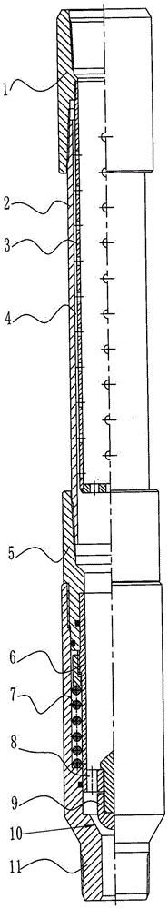
[0008] Attached below figure 1 Embodiments of the present invention will be described.

[0009] As can be seen from the figure, the embodiment of the present invention includes a connecting head 5, a sliding sleeve 6, a spring 7, a valve core 9, and a valve body 11. The upper end of the sliding sleeve 6 rests on the shoulder inside the connecting head 5, so that the sliding sleeve 6 is limited position, the spring 7 is sleeved on the sliding sleeve 6, the upper end surface of the spring 7 is supported on the outer shoulder of the sliding sleeve 6, the valve core 9 is installed in the middle position of the bottom of the sliding sleeve 6, the bottom surface of the sliding sleeve 6 has a communication hole 8, the valve The upper part of the body 11 is connected with the lower part of the connecting head 5, so that the lower end face of the spring 7 is supported on the inner shoulder of the valve body 11, and there is a valve port 10 in the lower part of the valve body 11, and th...


PUM


Abstract

The invention relates to an oil casing pipe communicating device for a separate-layer fracturing string. The upper end of a sliding sleeve is propped against a shoulder inside a connector, the sliding sleeve is sleeved with a spring, the upper end surface of the spring is supported on an outer shoulder of the sliding sleeve, a valve core is mounted in the middle of the bottom of the sliding sleeve, a communicating hole is formed in the bottom surface of the sliding sleeve, the upper part of a valve body is connected with the lower part of the connector, the lower end surface of the spring is supported on a shoulder in the valve body, a valve opening is formed in the lower part of the valve body, the valve opening and the valve core cooperate for sealing and can stop a liquid flow from the upper part, the upper part of a hanging basket is connected onto a middle thread of an upper joint, a lower thread of the upper joint is connected with the upper part of a connecting pipe, an annular space is formed between the connecting pipe and the hanging basket, a baffle is arranged at the bottom of the hanging basket, sieve holes are formed in a pipe body, and the lower part of the connecting pipe is connected with the upper part of the connector. After construction is completed, the valve core leaves the valve opening when a string is lifted, the fracturing string is communicated, the liquid flow in the string leaks into a well, so that environmental pollution can be prevented, and operation construction is convenient.

Description

technical field [0001] The invention is a tool used on the oil field fracturing construction pipe string, which is used to connect the oil casing when sealing the pipe string and pulling out the fracturing pipe string. . Background technique [0002] When the oilfield is divided into layers, it is necessary to open or close the layered sandblaster. The opening or closing of the sandblaster is realized by hydraulic pressure. It is necessary to inject high-pressure liquid flow into the interior to realize the opening or closing of the sandblaster. Therefore, the sandblaster needs to be opened or closed. , the bottom of the fracturing string needs to be sealed, and the bottom of the fracturing string also needs to be able to catch the sliding sleeve that opens the fracturing tool. The existing sealing tools matched with the fracturing string can achieve sealing, but in the When the fracturing string is exited, the liquid in the string cannot be drained into the casing, causing...

Claims


Application Information

Patent Timeline
Patent Type & Authority Applications(China)
IPC IPC(8): E21B17/08E21B34/08E21B43/26
CPCE21B17/08E21B34/08E21B43/26
Inventor 马宝龙曲绍坤曲哲荣雷杨永刚刘林涛宋沙沙
Owner 东营市兆鑫工贸有限责任公司
Why Eureka
Try Eureka