Flow control valve for gas stove

A technology for flow control valves and gas stoves, applied in valve details, safety valves, balance valves, etc., can solve the problems of reduced panel strength, flow into the interior of the cooker, and affect the aesthetics of the cooker, achieve a good linear relationship, eliminate transmission errors, Ease of implementation

Inactive Publication Date: 2016-04-13
NINGBO FOTILE KITCHEN WARE CO LTD
View PDF5 Cites 3 Cited by
  • Summary
  • Abstract
  • Description
  • Claims
  • Application Information

AI Technical Summary

Problems solved by technology

[0002] Nowadays, the gas flow adjustment of domestic gas stoves widely adopts the manual adjustment structure of cock valves, which leads to the existing stoves having to open holes on the panel to extend the gas flow adjustment handle out of the panel. This structure will lead to panel stoves such as glass or ceramics. The strength of the panel is reduced, and at the same time, it is easy for the water on the table to flow into the inside of the cooker through the hole where the handle protrudes, causing the inside of the cooker to become dirty and corrode the parts.
This structure not only affects the overall aesthetics of the cooker, but also greatly shortens the normal service life of the cooker, and also restricts the development of the cooker in the direction of intelligence and automation.

Method used


Image

  • Flow control valve for gas stove
  • Flow control valve for gas stove
  • Flow control valve for gas stove

Examples


Embodiment Construction

[0020] The present invention will be further described in detail below in conjunction with the accompanying drawings and embodiments.

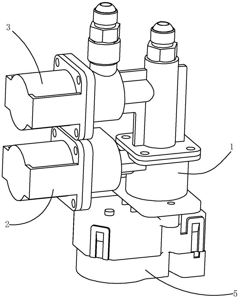
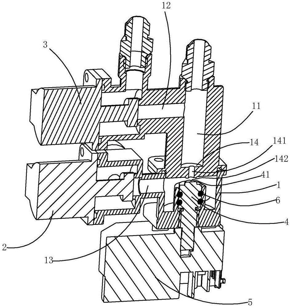
[0021] Such as figure 1 , 2 The gas stove flow control valve shown includes a valve body 1. The valve body is provided with an inner ring gas outlet channel 11 connected to the inner ring burner, an outer ring gas outlet channel 12 connected to the outer ring burner, and the outer ring gas outlet channel 12 is connected to the inner ring. The air outlet passage 11 communicates; the valve body 1 is also provided with an air intake passage 13 connected with the gas source; the air intake passage 13 is provided with a first electromagnetic valve 2 that opens or closes the gas entering the valve body from the air intake passage, so The outer ring air outlet channel 12 is provided with a second solenoid valve 3 that opens or closes the gas flowing out of the outer ring air outlet channel; the valve body 1 is provided with a partition 14 so that th...


PUM


Abstract

The invention relates to a flow control valve for a gas stove. The flow control valve comprises a valve body, wherein an inner ring gas outlet passage communicated with an inner ring combustor and an outer ring gas outlet passage communicated with an outer ring combustor are formed in the valve body; the outer ring gas outlet passage is communicated with the inner ring gas outlet passage; a gas inlet passage communicated with a gas source is also formed in the valve body. The flow control valve is characterized in that a partition board is arranged in the valve body, so as to divide the interior of the valve body into two spaces; one space, on one side of the partition board, in the valve body is communicated with the gas inlet passage; the other space, on the other side of the partition board, in the valve body is communicated with the inner ring gas outlet passage; a through hole is formed in the partition board; an adjusting rod opposite to the through hole in the partition board is arranged in the valve body, and is connected with an electric driving mechanism, so that the clearance between the adjusting rod and the partition board can be changed under the driving of the electric driving mechanism. Compared with the prior art, the flow control valve has the advantages that stepless adjusting of gas flow can be realized; the linear relationship between the adjusting angle and the gas flow can be excellent; the structure is novel; the implementation is convenient.

Description

technical field [0001] The invention relates to a flow control valve, in particular to a gas stove flow control valve. Background technique [0002] Nowadays, the gas flow adjustment of household gas stoves widely adopts the manual adjustment structure of cock valves. As a result, the existing stoves must have holes on the panels to extend the gas flow adjustment handles out of the panels. This structure will lead to panel stoves such as glass or ceramics. The strength of the panel is reduced, and at the same time, it is easy for the water on the table to flow into the inside of the cooker through the hole protruding from the handle, causing the inside of the cooker to be dirty and corrode parts. This structure not only affects the overall aesthetics of the cooker, but also greatly shortens the normal service life of the cooker, and also restricts the development of the cooker in the direction of intelligence and automation. [0003] For this reason, an automatic adjustment...

Claims


Application Information

Patent Timeline
Patent Type & Authority Applications(China)
IPC IPC(8): F16K31/04F16K17/20
CPCF16K31/04F16K17/20
Inventor 严力峰郑军妹吴丽波茅忠群诸永定
Owner NINGBO FOTILE KITCHEN WARE CO LTD
Why Eureka
Try Eureka