Surveillance camera

A monitoring camera and camera technology, applied in the field of monitoring cameras, can solve problems such as waste of resources, inconvenient adjustment, and waste, and achieve the effects of resource and cost saving, convenient adjustment, and simple structure

Inactive Publication Date: 2016-04-13
CHENGDU KECHUANGGU TECH CO LTD
View PDF5 Cites 13 Cited by
  • Summary
  • Abstract
  • Description
  • Claims
  • Application Information

AI Technical Summary

Problems solved by technology

For example, when there are traffic accidents or public security problems in individual locations, it is necessary to obtain surveillance images of specific locations. Due to the small number of monitoring equipment in the current urban construction, there are many dead spots in the observation range, and this requirement cannot be realized.
[0003] Most of the tra

Method used


Image

  • Surveillance camera

Examples


Embodiment 1

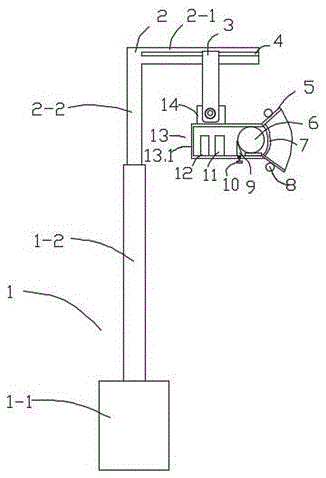
[0021] Such as figure 1 As shown, this embodiment provides a surveillance camera, including a camera body 13 and a mounting bracket 2, characterized in that a hydraulic lifting device 1 is connected under the mounting bracket 2, and the hydraulic lifting device 1 includes a hydraulic adjustment cylinder 1-1 And the hydraulic adjustment rod 1-2, the two ends of the hydraulic adjustment rod 1-2 are respectively connected to the hydraulic adjustment cylinder 1-1 and the installation bracket 2, the installation bracket 2 includes an integrally formed horizontal support plate 2-1 and a vertical support Plate 2-2, the vertical support plate 2-2 is connected with the top end of the hydraulic adjustment rod 1-2, the transverse support plate 2-1 is provided with a chute 4, the shape of the cross section of the chute 4 is a non-return Groove, chute 4 is clamped with camera fixing device 3, and camera fixing device 3 can move back and forth along chute 4, and the other end of camera fixi...

Embodiment 2

[0023] This embodiment is further improved on the basis of embodiment 1, specifically,

[0024] The pixel of the monitoring camera is not less than 250,000.

[0025] Described lighting lamp 8 is 6.

[0026] The inner wall of the camera installation box 13.1 is provided with an interference signal shielding layer.

[0027] The rear of the camera 6 in the camera installation box 13.1 is provided with a focus adjustment block 9, the focus adjustment block 9 is a wedge-shaped structure, and the wedge-shaped surface of the focus adjustment block 9 is arranged directly behind the camera 6. The bottom of the focal length adjustment block 9 is connected with an adjusting bolt 10 passing through the camera installation box 13.1, a sealing ring is arranged between the camera protection glass 7 and the camera installation box 13.1, and the adjustment bolt 10 is installed with the camera installation box 13.1. The boxes 13.1 are hermetically connected by connecting bearings.

[0028] T...


PUM


Abstract

The invention discloses a surveillance camera and relates to the technical field of image acquisition. The surveillance camera comprises a cameral body and a mounting support, wherein the lower part of the mounting support is connected with a hydraulic lifting device, the hydraulic lifting device comprises a hydraulic adjustment cylinder and a hydraulic adjustment rod, and two ends of the hydraulic adjustment rod are connected to the hydraulic adjustment cylinder and the mounting support; the mounting support comprises a transverse supporting plate and a longitudinal supporting plate which are integrally formed, the longitudinal supporting plate is connected with the top end of the hydraulic adjustment rod, a sliding chute is formed in the transverse supporting plate, the cross section of the sliding chute is shaped like a big-end-down non-return groove, a camera fixing device is clamped in the sliding chute and can move along the sliding chute back and forth, and a camera body is connected at the other end of the camera fixing device. The surveillance camera has the advantages of simple structure, adjustability in height and convenience in adjustment of shooting distance and shooting angle.

Description

technical field [0001] The present invention relates to the technical field of routers, and more specifically relates to a surveillance camera. Background technique [0002] With the advancement of science and technology, urban construction promotes high-tech intelligence. Nor are road safety concerns limited to the inconveniences of poor lighting. For example, when there is a traffic accident or public security problem in a certain location, it is necessary to obtain surveillance images of a specific location. Due to the small number of monitoring equipment in the current urban construction and the large number of dead spots in the observation area, this requirement cannot be realized. [0003] Most of the traditional cameras in the prior art are fixed installations, and it is inconvenient to disassemble the mounting frame and the camera body. After the camera is partially damaged, it needs to be replaced as a whole instead of a part. After it is damaged, it cannot be mov...

Claims


Application Information

Patent Timeline
IPC IPC(8): F16M11/04F16M11/18F16M11/24F21V33/00G03B17/56H04N5/225
CPCG03B17/561G03B17/566F16M11/045F16M11/18F16M11/242F21V33/0052F16M2200/08H04N23/50
Inventor 吴凯刘菲张建李成
Owner CHENGDU KECHUANGGU TECH CO LTD
Why Eureka
Try Eureka