Heat conduction oil boiler

A heat-conducting oil boiler and furnace technology, which is applied in the boiler field, can solve the problems of furnace tube wear, heavy weight, and large furnace roof weight, and achieve the effect of reducing the amount of particles

Inactive Publication Date: 2016-04-13
BEIJING ONE A HI TECH ENERGY TECH CO LTD
View PDF10 Cites 0 Cited by
  • Summary
  • Abstract
  • Description
  • Claims
  • Application Information

AI Technical Summary

Problems solved by technology

[0004] The conventionally designed furnace roof is made of all refractory materials, which is heavy and complex in structure. At the same time, due to high temperature, especially when the temperature changes frequently, the furnace roof will collapse due to different expansions and the furnace tube will be worn.
Furnace roof is heavy, poor thermal stability, easy to damage

Method used


Image

  • Heat conduction oil boiler
  • Heat conduction oil boiler
  • Heat conduction oil boiler

Examples


Embodiment Construction

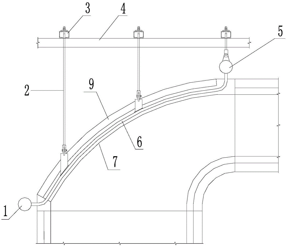
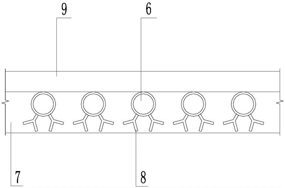
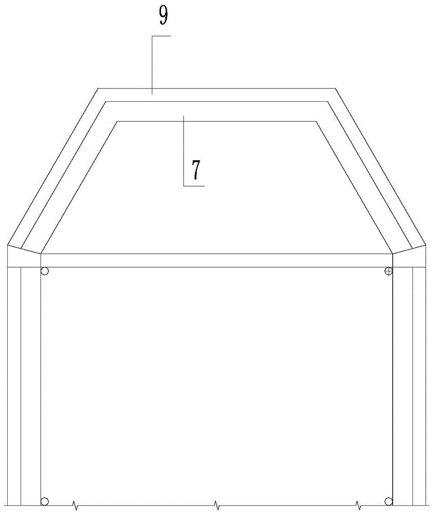
[0026] Such as Figure 1-3 As shown, a heat-conducting oil boiler according to an embodiment of the present invention includes: a furnace, and a heat dissipation device installed at the furnace; the furnace is provided with a furnace top and a furnace side, and the furnace top and the furnace side The part is in the shape of a smooth transition tapered mouth, and the two sides of the tapered mouth shape are provided with an inlet and an outlet. The cross-sectional shape of the inlet is equal to the top cross-section of the furnace. A separator is installed at the outlet, and the cross-sectional shape of the outlet is equal to the inlet of the separator. The heat dissipation device includes a plurality of ceiling pipes evenly installed in the top of the furnace, one end of the ceiling pipe is installed with a cooling medium inlet header, and the other end is installed with a cooling medium outlet header, and the ceiling pipe passes through the hanging device Connect with beam...


PUM


Abstract

The invention relates to a heat conduction oil boiler which comprises a hearth and a heat dissipating device. The hearth is provided with a hearth top and a hearth side portion. The hearth top and the hearth side portion are in the shape of a smooth-transition gradually-shrunk opening. An inlet and an outlet are formed in the two sides of the shape of the gradually-shrunk opening. The shape of the cross section of the inlet is the same as that of the cross section of the hearth top. A separator is installed on the outlet, and the shape of the section of the outlet is the same with that of an inlet of the separator. The heat dissipating device comprises a plurality of roof tubes evenly installed in the hearth top. One ends of the roof tubes are provided with a cooling medium inlet header, and the other ends of the roof tubes are provided with a cooling medium outlet header. The roof tubes are connected with a beam through hanging devices. The heat conduction oil boiler has the beneficial effects that the two ends of the roof tubes are connected with the cooling medium inlet header and the cooling medium outlet header, the hearth interior can be cooled, the hearth is in the shape of the smooth-transition gradually-shrunk opening, the shape of the section of the outlet of the gradually-shrunk opening is the same as that of the inlet of the separator so that the number of particles, brought into the separator, of smoke can be reduced, and the advantages of firmness, durability and the like are achieved.

Description

technical field [0001] The invention relates to the technical field of boilers, in particular to a heat-conducting oil boiler. Background technique [0002] The top of the circulating fluidized bed boiler is designed to face directly. The amount of particles in the soot that the flue gas is easy to bring into the separator affects the separation of the particles in the soot. The existing structure tends to cause a situation where the local ash concentration at the outlet of the furnace is too high, which accelerates the wear of the nearby heating surface. [0003] The furnace of the heat-conducting oil furnace adopts a coil structure, and the coil is arranged horizontally. The flow direction of the particles is perpendicular to the direction of the tube arrangement, and the wear of the particles on the tube wall will be serious. The wear of the structural surface of the heat transfer oil furnace outlet is a very big safety hazard, and the burst of the tube may cause a fire....

Claims


Application Information

Patent Timeline
Patent Type & Authority Applications(China)
IPC IPC(8): F23M5/08
CPCF23M5/08
Inventor 王友才曹剑陈宣
Owner BEIJING ONE A HI TECH ENERGY TECH CO LTD
Why Eureka
Try Eureka