High-precision optical signal phase demodulation system and demodulation method

An optical signal and phase demodulation technology, which is applied in the direction of transmitting sensing components, converting sensor output, and measuring devices with optical devices, can solve the problems of constructing related signals, increasing the number of optical signal channels, and the impact of associated amplitude modulation, etc., to achieve sensor signal Processing performance optimization, elimination of associated amplitude modulation, and improvement of system stability and phase resolution

Active Publication Date: 2016-04-13
HARBIN ENG UNIV
View PDF12 Cites 12 Cited by
  • Summary
  • Abstract
  • Description
  • Claims
  • Application Information

AI Technical Summary

Problems solved by technology

The core idea of ​​the above methods is to use the correlation between multi-channel signals to eliminate irrelevant noise, so as to obtain better output results. However, in the construction of related signals, the number of optical signal channels is increased, which will undoubtedly bring to additional environmental factors;
[0004] In addition, AntonioL.Deus in the United States, GeraldL.Assard et al. proposed an improved cross-differential multiplication method (US6580314B1). This method does not need to add an additional optical path structure, and uses the fundamental frequency component in the sensing signal of one path, and the square root of the multiplier component As a result, it is introduced into the solution process to eliminate part of the noise, but this method is easily affected by the associated amplitude modulation. When the fundamental frequency component and the multiplier frequency component fluctuate greatly, the system output quality will decline; Yang Jun et al. of Harbin Engineering University also proposed a method Use the method of ellipse fitting correction (CN201510293443.9) and an optical interference phase demodulation method (201510293443.3) to increase the dynamic range and enhance the stability to correct the influence of the amplitude modulation associated with the light source

Method used


Image

  • High-precision optical signal phase demodulation system and demodulation method
  • High-precision optical signal phase demodulation system and demodulation method
  • High-precision optical signal phase demodulation system and demodulation method

Examples


Embodiment

[0145] Embodiment——Add N channels to suppress system noise

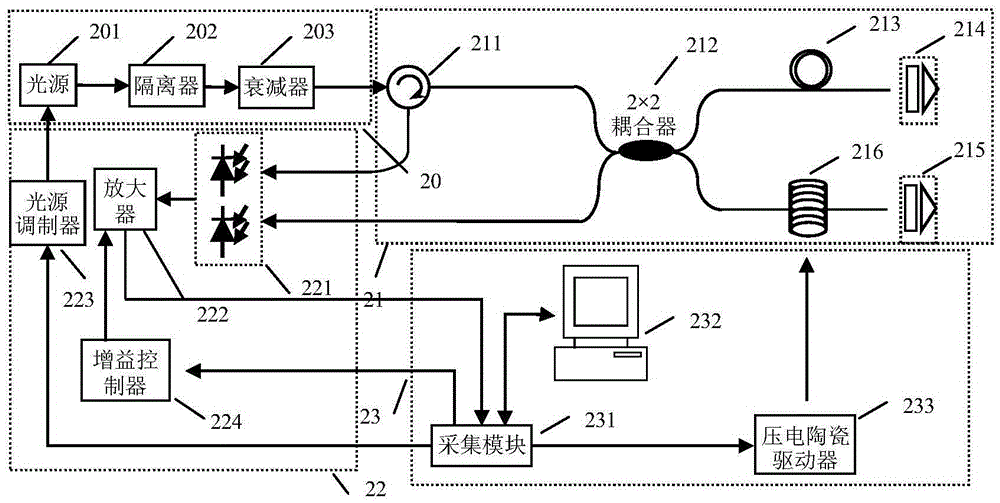
[0146] Interferometer devices such as figure 2 As shown, the device selection and parameters of the interferometer measurement device are as follows:

[0147] 1. The central wavelength of the light source 201 is 1550nm, the half-spectrum width is greater than 45nm, and the fiber output power is greater than 1-10mW;

[0148] 2. The working wavelength of the fiber optic isolator 202 is 1550nm±5nm, the insertion loss is ≤1.0dB (at 23°C working temperature), and the return loss is ≥55dB;

[0149] 3. The working wavelength of the circulator 211 is 1550nm&1310nm, the insertion loss is 1.0dB, the isolation is 28dB, the directivity is 50dB, the working temperature is 0~70℃, and the return loss is 45dB;

[0150] 4. The working wavelength of the first Faraday rotation mirror 214 and the second Faraday rotation mirror 215 is 1550nm±5nm, the insertion loss is 0.6dB, the Faraday rotation angle is 90°, the rotation angle error ...


PUM


Abstract

The invention discloses a high-precision optical signal phase demodulation system and a demodulation method. The system comprises a front-end acquisition module, a multipath phase lock module and a data demodulation module. The front-end acquisition module comprises a data acquisition submodule and a phase modulation wave submodule. The multipath phase lock module comprises N multipliers and N filters. The data demodulation module comprises N Hilbert transform submodules, N phase accumulation submodules and a downsampling smoothing filtering submodule. Independent uncorrelated demodulation can be carried out; in the final demodulation result, actual phase change in a light path is in correlation; the demodulation process and externally-introduced noise have no correlation; higher SNR (signal to noise ratio) can be obtained through an accumulated average noise reduction method; optical signal phase demodulation precision is effectively improved; and the demodulation system and demodulation method can be widely applied to the field of high-precision optical fiber measurement and optical fiber sensing and the like.

Description

technical field [0001] The invention belongs to the field of optical (fiber) interferometer measurement, in particular to a high-precision optical signal phase demodulation system and demodulation method. Background technique [0002] Fiber optic sensors have the advantages of high sensitivity, large dynamic range, and convenient deployment in vibration signal detection. Among them, phase fiber optic sensors are widely used in underwater acoustic signal monitoring, seismic signal recording and other fields. The working principle of the phase fiber optic sensor is to calibrate the corresponding physical quantity by measuring the phase change in the optical path caused by physical quantities such as stress, strain, displacement and acceleration. How to accurately measure the phase information becomes the key to the sensor. In 1982, the U.S. Naval Laboratory KIRKENDALLCK, DANDRIDGEA. et al. proposed a phase generation carrier (PGC) method to calculate the phase change of the in...

Claims


Application Information

Patent Timeline
Patent Type & Authority Applications(China)
IPC IPC(8): G01D5/353
CPCG01D5/35306
Inventor 彭峰侯璐吴冰苑勇贵侯长波
Owner HARBIN ENG UNIV
Why Eureka
Try Eureka