
Method and system for detecting leading edge of pulse waveform based on straight line fitting

A straight line fitting and pulse waveform technology, which is applied in pulse characteristic measurement, general control system, control/regulation system, etc., can solve the problems of low detection accuracy of waveform frontier and inapplicable detection accuracy, etc.

Active Publication Date: 2016-04-13
WATCHDATA SYST
View PDF6 Cites 11 Cited by
  • Summary
  • Abstract
  • Description
  • Claims
  • Application Information

AI Technical Summary

Problems solved by technology

This method has two disadvantages. One is that it is only applicable to the application scenarios where the pulse amplitude changes slowly, but not the application scenarios where the pulse amplitude changes rapidly. The detection accuracy is low
The above two factors make the waveform frontier detection method based on a fixed threshold unsuitable for applications where the pulse amplitude changes rapidly and requires high detection accuracy.

Method used


Image

  • Method and system for detecting leading edge of pulse waveform based on straight line fitting
  • Method and system for detecting leading edge of pulse waveform based on straight line fitting
  • Method and system for detecting leading edge of pulse waveform based on straight line fitting

Examples


specific Embodiment approach

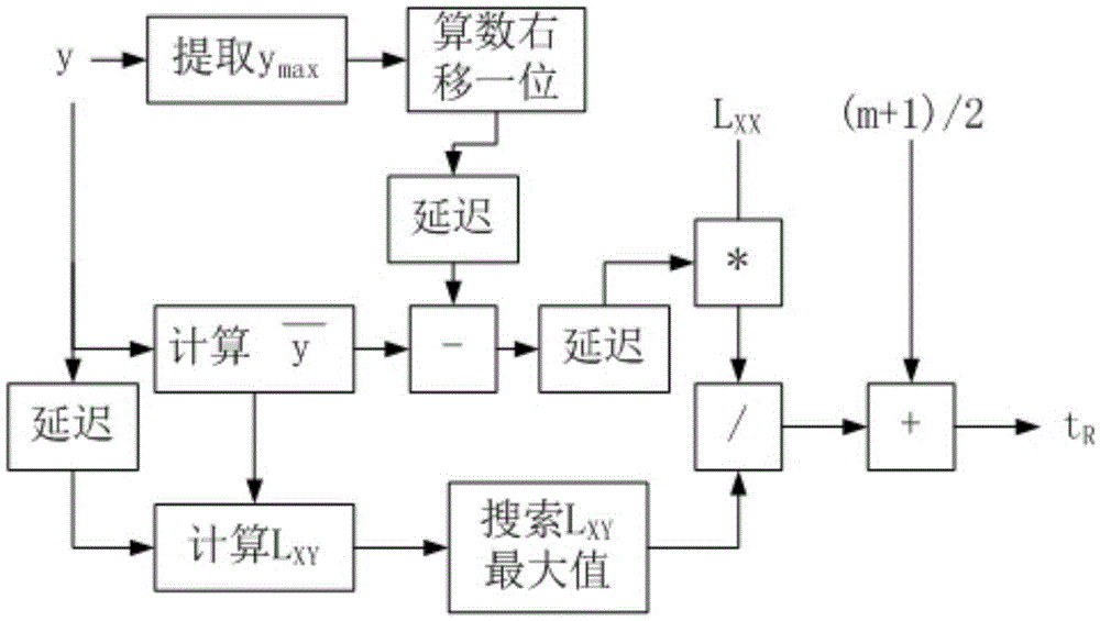
[0081] Such as figure 2 Shown, a kind of specific implementation of the method for the pulse waveform frontier detection based on straight line fitting, comprises the following steps:

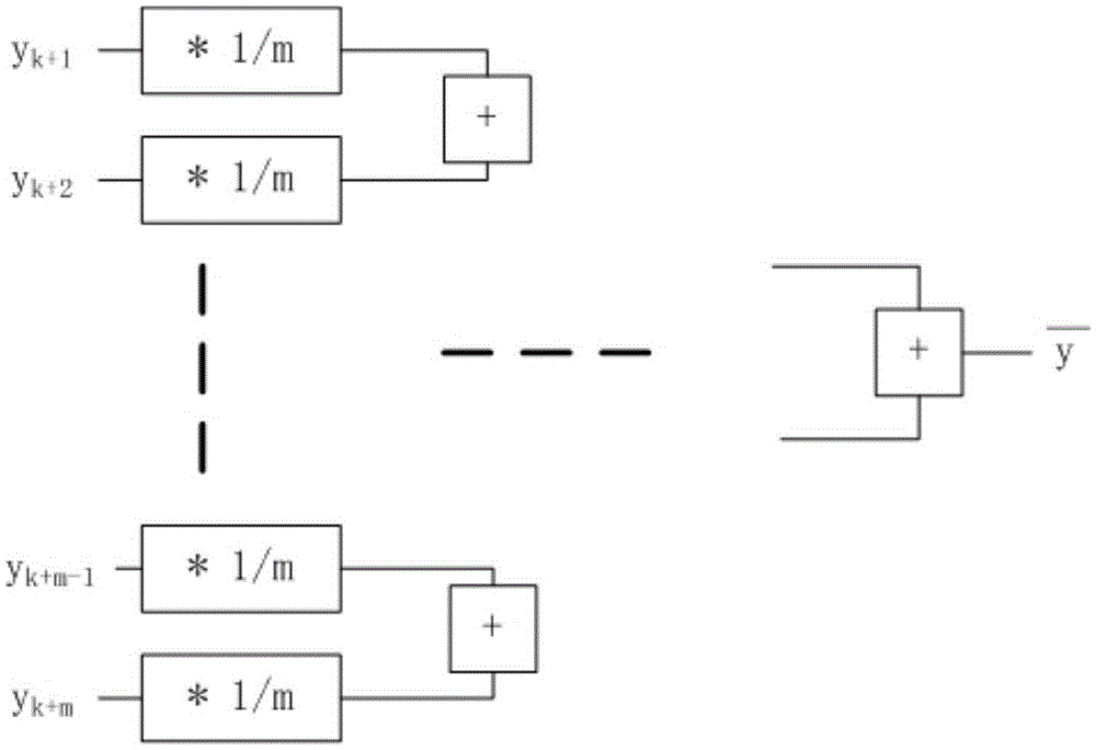
[0082] 1) Perform an average operation on the m waveform sampling points in the window, and take the maximum value on the n sampling points;

[0083] 2) Perform an arithmetic right shift operation on the maximum value of the waveform sampling points in the window obtained, which is equivalent to dividing by 2, then delaying and waiting for the average value Calculation results;

[0084] 3) Delay the waveform sampling points and wait for the average value Calculate the result so that L XY calculate;

[0085] 4) Calculate L XY , and then continuously search for L XY The maximum value of L XY_MAX ;

[0086] 5) calculate Then delay computing the result, waiting for L XY maximum result;

[0087] 6) Multiply the result of step 5) by L XX ;

[0088] 7) Divide the calculation result of...


PUM


Abstract

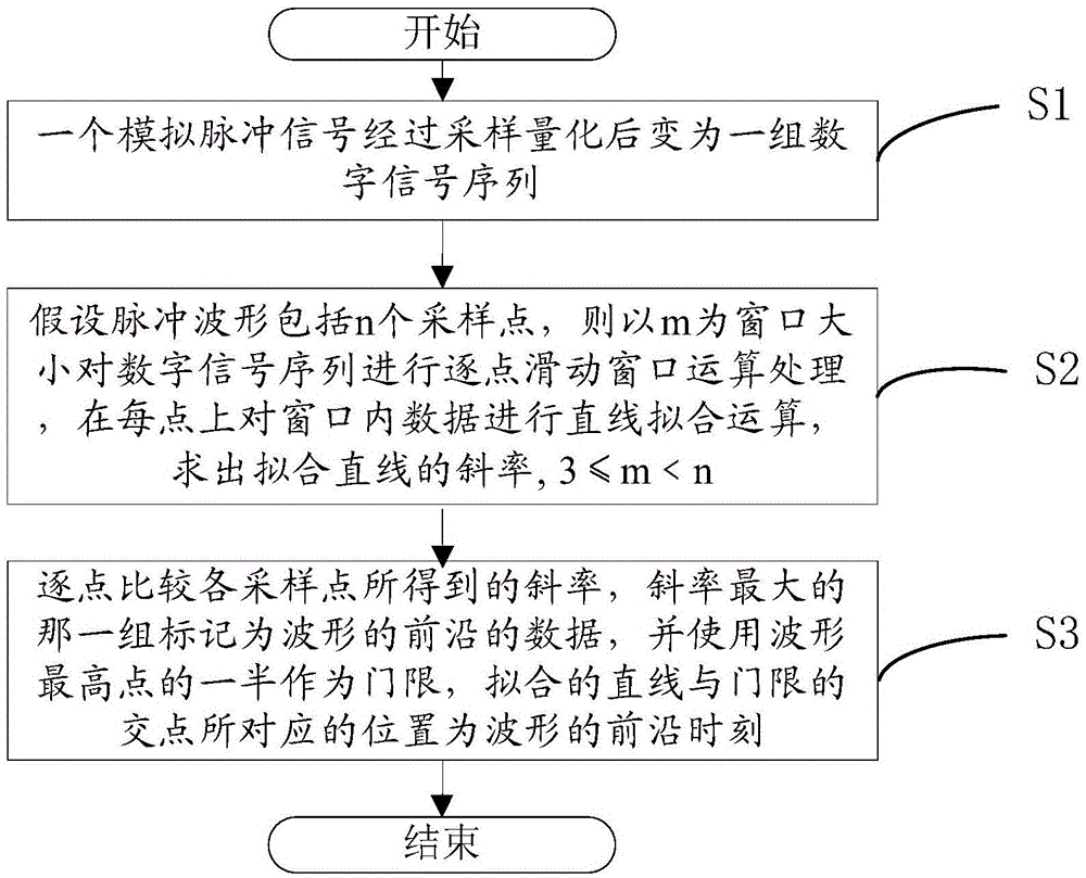
The invention relates to a method and a system for detecting a leading edge of a pulse shape based on straight line fitting, belonging to the waveform leading edge detection technology field. The method comprises steps of converting an analog pulse signal to a group of digital signal sequences after sampling quantization, supposing that the pulse waveform comprises n sampling points, using an m as a window size to perform point-by-point sliding window operation processing on the digital signal sequence, performing straight line fitting operation on the data inside the window on each point to solve an inclination rate of the fitted straight line, wherein 3<=m<n, comparing the inclination rates of the sampling points point by point, marking the group having the maximum inclination rate as the data of the waveform leading edge, and using the half of the highest point of the waveform as a threshold, wherein the position corresponding to the intersection point between fitted straight line and the threshold is the leading edge moment of the waveform. The invention is high in accuracy, small in calculation amount, fast in calculation speed and easy to implement.

Description

technical field [0001] The invention belongs to the technical field of waveform frontier detection after pulse waveform ADC sampling, and in particular relates to a method and system for pulse waveform frontier detection based on straight line fitting. Background technique [0002] Waveform leading edge detection is mainly used to calculate the waveform leading edge moment. By improving the existing waveform frontier detection technology, the accuracy of echo ranging can be improved. [0003] The existing pulse waveform ADC (abbreviation of analog-to-digital converter, analog-to-digital converter) detects the waveform leading edge after sampling, which is usually a processing method based on a fixed threshold. After the pulse waveform is enlarged and shaped, it is compared with the fixed threshold value to determine the position of the front edge of the waveform. This method has two disadvantages. One is that it is only applicable to the application scenarios where the pul...

Claims


Application Information

Patent Timeline
IPC IPC(8): G01R29/02G05B19/042
CPCG01R29/02G05B19/0425G05B2219/2612
Inventor 吴限
Owner WATCHDATA SYST
Learn More