Bipolar plate for fuel cell

A fuel cell and bipolar plate technology, which is applied to fuel cells, fuel cell components, circuits, etc., can solve problems such as fluid inflow, closed inlet and outlet, and achieve the effect of ensuring balance and improving untimely supply.

Active Publication Date: 2016-04-13
武汉理工新能源有限公司
View PDF5 Cites 12 Cited by
  • Summary
  • Abstract
  • Description
  • Claims
  • Application Information

AI Technical Summary

Problems solved by technology

However, when the bipolar plates are affected by the clamping force, the header pipe 9 is easy to fit together, thus causing the inlet and outlet to be closed
And because the diversion groove 10 is a closed structure, the fluid cannot flow in from the diversion groove 10.

Method used


Image

  • Bipolar plate for fuel cell
  • Bipolar plate for fuel cell
  • Bipolar plate for fuel cell

Examples


Embodiment 1

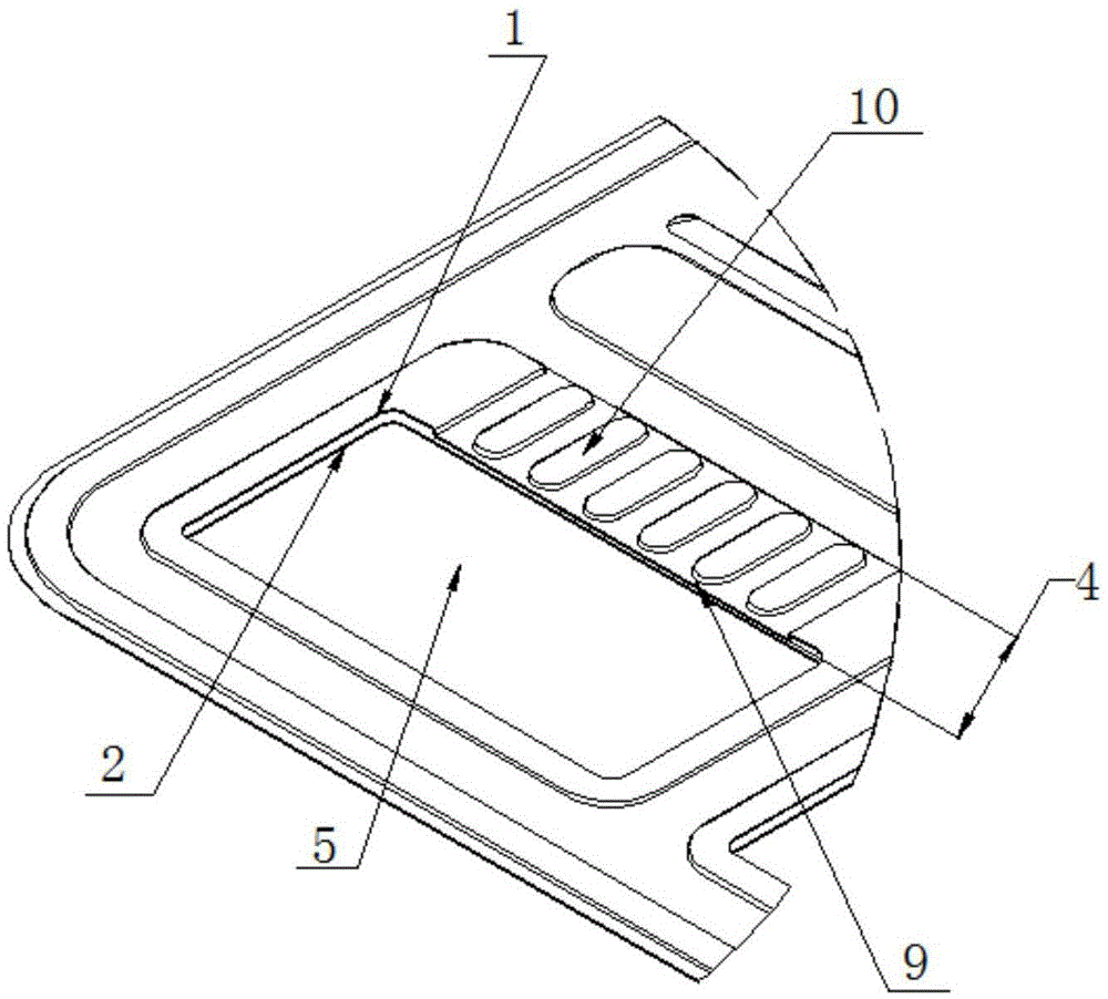
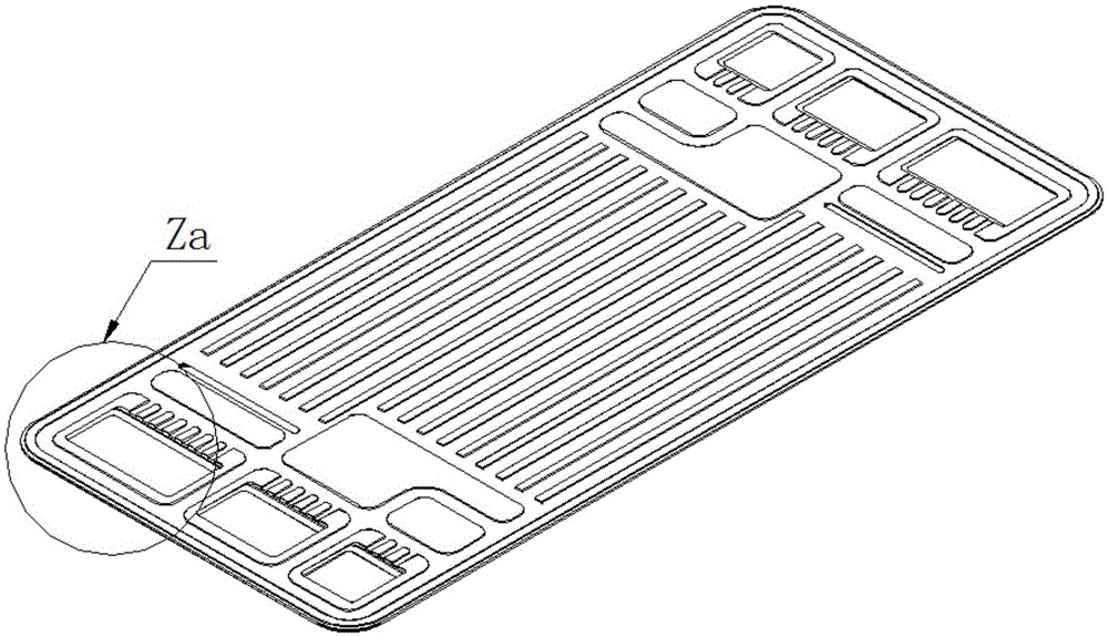
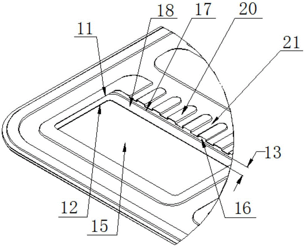
[0025] Such as figure 2 with image 3 As shown, it is a fuel cell bipolar plate provided in this embodiment, which includes a first plate 11, a second plate 12, and a manifold 15. The first electrode plate 11 is an anode hydrogen-conducting flow field plate, the second electrode plate 12 is a cathode air-conducting flow field plate, and a cooling fluid interlayer is formed between the first electrode plate 11 and the second electrode plate 12. The fluid inlet and outlet area of ​​the first electrode plate 11 is provided with a plurality of diversion grooves 20 adjacent to the protrusions of the manifold 15. The second plate 12 includes an area 13 composed of a header pipe 17 and a header pipe 18. A plurality of protruding diversion grooves 20 are arranged at intervals, and a pressure-resistant connecting plate 21 is formed between every two adjacent diversion grooves 20. One end of each diversion groove 20 is set as a fluid inlet and outlet 16, and each diversion groove 20 Th...

Embodiment 2

[0032] Such as Figure 4 with Figure 5 As shown, it is a fuel cell bipolar plate provided by this embodiment, which is roughly the same as Embodiment 1, except that the projection line of the corresponding position of the second plate 12 is located in the fluid of the plurality of flow channels 20 The right side of the projection line of the longitudinal section defined by the inlet and outlet 16 is the side close to the flow field plate.

[0033] The design of the fuel cell bipolar plate, which is beneficial to the steady-state gas and water supply, can effectively reduce fuel loss and avoid water blocking. Improve fuel utilization and improve fuel cell efficiency.


PUM


Abstract

The invention relates to a bipolar plate for a fuel cell. The bipolar plate for the fuel cell comprises a first polar plate and a second polar plate, wherein the first polar plate is an anode hydrogen guide flow field plate; the second polar plate is a cathode air guide flow field plate; a cooling fluid guide interlayer is formed between the first polar plate and the second polar plate; a plurality of raised guide channels adjacent to a branch pipe are arranged in a fluid inlet and outlet region of the first polar plate; the plurality of raised guide channels are arranged at intervals; a compressive connection plate is formed between every two adjacent guide channels; fluid inlet and outlet are formed in one end of each guide channel; a closed end is arranged at the other end of each guide channel; the fluid inflows from the fluid inlet and outlet of each guide channel and inflows from a hollow cavity formed between the compressive connection plate and the second polar plate; and the longitudinal sections defined by the fluid inlets and outlets of the plurality of guide channels are vertical to the flow direction of the fluid. According to the bipolar plate structure for the fuel cell provided by the invention, the problem of water and gas plugging caused by closing of a master pipe orifice of the flow field plates due to uneven stress on the fuel cell in the assembly process can be effectively solved.

Description

Technical field [0001] The invention relates to the technical field of fuel cells, in particular to a fuel cell bipolar plate. Background technique [0002] The proton exchange membrane fuel cell has the advantages of cold start at room temperature, high conversion efficiency, high volumetric power density, zero product pollution, etc., so it has become a research hotspot in today's international society. Compared with the general chemical power source, it has a complicated structure. In addition to the fuel cell stack itself, it also includes some auxiliary equipment. Fuel cell system power density and battery conversion efficiency are two important indicators for evaluating fuel cell performance. The volume and energy consumption of auxiliary equipment directly affect the overall power density of the fuel cell system. At the same time, the overall energy conversion efficiency of the fuel cell is reduced. [0003] At present, a single battery can generally generate a voltage of...

Claims


Application Information

Patent Timeline
Patent Type & Authority Applications(China)
IPC IPC(8): H01M8/026H01M8/0267
CPCH01M8/026H01M8/0267Y02E60/50
Inventor 潘牧宛朝辉艾勇诚范卫东周芬
Owner 武汉理工新能源有限公司
Why Eureka
Try Eureka