Tool holding fixture

A tool holder and tool technology, which is used in the attachment of tool holders, tools for lathes, shrink connections, etc., to achieve the effects of rapid speed change, increased productivity, and less energy input

Active Publication Date: 2016-04-13
HAIMER
View PDF13 Cites 1 Cited by
  • Summary
  • Abstract
  • Description
  • Claims
  • Application Information

AI Technical Summary

Problems solved by technology

However, since the receiving body made of steel must have certain dimensions in order to achieve the required rigidity, the known toolholders also have a relatively high mass and a correspondingly large mass moment of inertia
The drives and the tool changing system must therefore also be dimensioned accordingly

Method used


Image

  • Tool holding fixture
  • Tool holding fixture
  • Tool holding fixture

Examples


Embodiment Construction

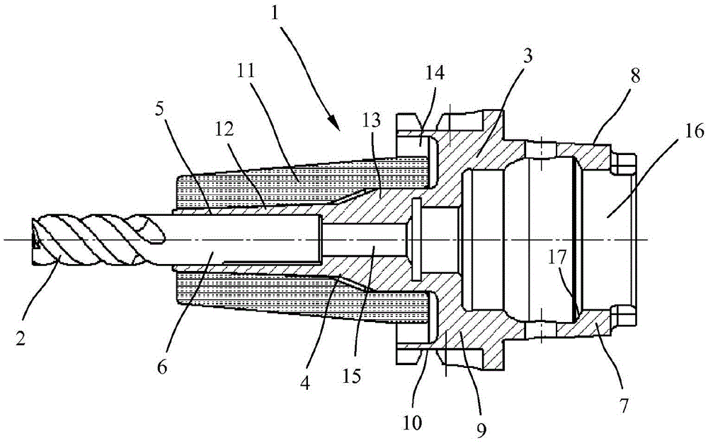
[0032] exist figure 1shows a tool holder 1 here with an HSK interface for non-positive clamping of drills, milling cutters, grinding tools or other rotary-driven tools 2 . The tool holder 1 is formed in the exemplary embodiment shown as a thermotechnical clamping chuck and comprises a rotationally symmetrical receptacle 3 , which has a receiving opening with a shank 6 for the tool 2 at its tool-side front end. 5 and, at its machine-side rear end, a conical rear receiving region 7 with a conical outer clamping surface 8 here for receiving in the machine tool work spindle. The steel receiving body 3 also has a cylindrical central region 9 with a grip groove 10 for engaging a tool changer. A sleeve 11 made of carbon fiber-reinforced plastic (CFK) or another fiber-reinforced plastic is arranged on the front clamping region 4 of the receiving body 3 .

[0033] exist figure 1 In the exemplary embodiment shown, the sleeve 11 made of CFK is arranged with a force fit / interference fi...


PUM


Abstract

The invention relates to a tool holding fixture (1) for rotationally driven tools (2), said tool holding fixture comprising a rotationally symmetrical holding body (3) which has a front clamping portion (4) having a holding opening (5) for a tool shaft (6) of the tool (2), and a rear holding portion (7) to be held in a work spindle of a machine tool. To achieve a reduced mass, a lower mass moment of inertia and at the same time high stiffness, a sleeve (11) consisting of a fibre-reinforced plastic is arranged at least in the front clamping portion (4).

Description

technical field [0001] The invention relates to a tool holder / holder according to the preamble of claim 1 . Background technique [0002] This toolholder is used as an interface between the rotationally driven tool and the machine tool's work spindle. The tool holder should receive the tool in a precisely positioned manner for machining with high precision and be able to change the tool quickly. Known tool holders generally contain a steel receptacle with a front clamping region with a receptacle opening for a tool holder and a rear receptacle region for receiving in a machine tool spindle. Depending on the clamping system, the rear receiving area can be formed differently. However, since the steel receiving body must have certain dimensions in order to achieve the required rigidity, the known tool holders also have a relatively high mass and a correspondingly large mass moment of inertia. The drives and the tool changing system must therefore also be dimensioned accordin...

Claims


Application Information

Patent Timeline
Patent Type & Authority Applications(China)
IPC IPC(8): B23P11/00F16B4/00
CPCB23B31/117F16B4/006B23B2226/275B23B2231/24B23B2240/28Y10T279/17957Y10T279/17111Y10T29/49865B23B31/1179B23P11/025
Inventor K·波普J·艾尔格斯R·海德里希R·默克J·克林格尔
Owner HAIMER
Why Eureka
Try Eureka