Gas turbine and heat shield for a gas turbine

A technology for gas turbines and heat shields, applied in the direction of machines/engines, mechanical equipment, engine functions, etc., can solve problems such as gas turbine efficiency loss, and achieve the effect of reducing production costs

Inactive Publication Date: 2016-04-13
SIEMENS AG
View PDF6 Cites 0 Cited by
  • Summary
  • Abstract
  • Description
  • Claims
  • Application Information

AI Technical Summary

Problems solved by technology

However, excessively large radial slot structures lead to a significant loss of gas turbine efficiency

Method used


Image

  • Gas turbine and heat shield for a gas turbine
  • Gas turbine and heat shield for a gas turbine

Examples


Embodiment Construction

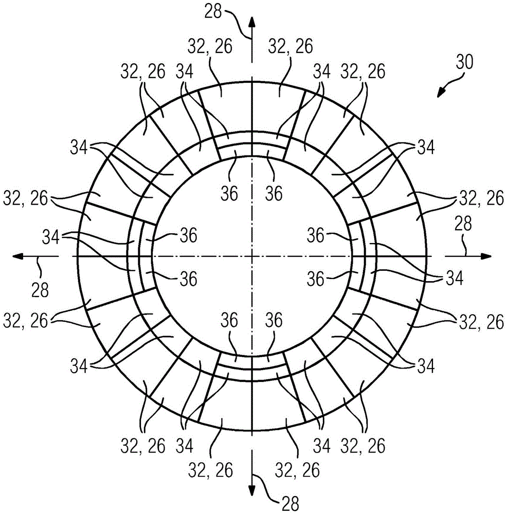
[0022] Mutually corresponding parts are indicated by the same reference numerals throughout the figures.

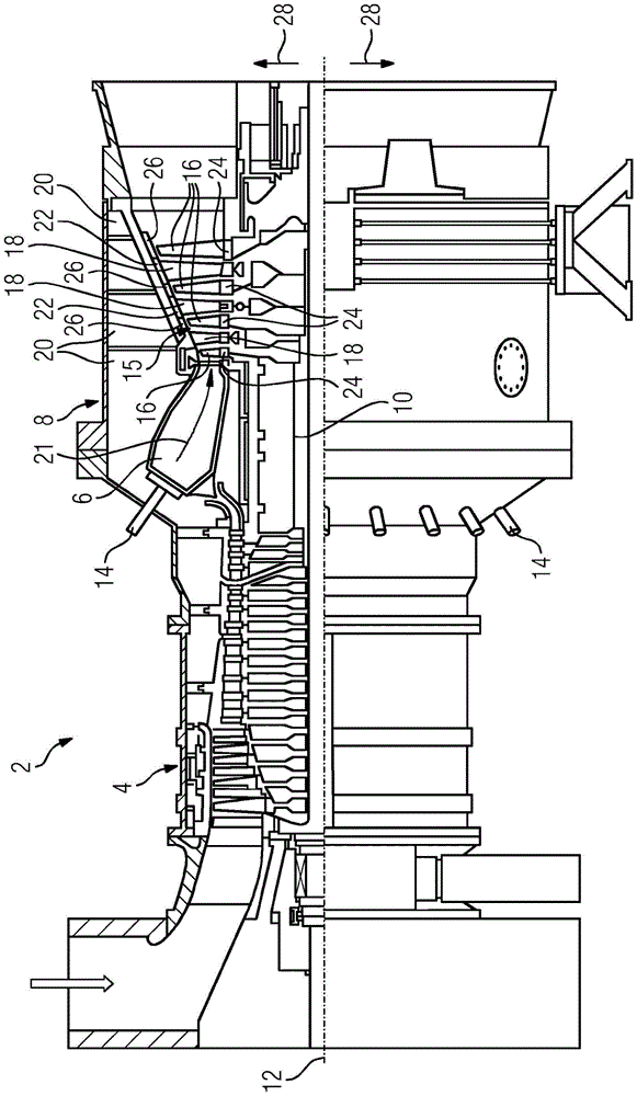
[0023] The gas turbine 2 described below by way of example is figure 1 Shown in , and in a manner known per se, is a compressor 4 , a combustion chamber 6 and a turbine unit 8 .

[0024] The combustion chamber 6 , formed in the form of an annular combustion chamber, is in this case equipped with several burners 14 for the combustion of liquid or gaseous fuels and opens into the hot gas duct 15 of the turbine unit 8 .

[0025]The turbine unit 8 and the compressor 4 are further arranged on a common turbine rod 10, also called a turbine rotor, to which a working machine (not shown) is also connected in a non-deterministic locking manner, and the turbine rod 10 is mounted It is made rotatable about the turbine shaft 12 . Further, the turbine unit 8 has a plurality of rotor blades 16 arranged in the hot gas duct 15 and connected to the turbine shaft 10 and rotatably mounted ...


PUM


Abstract

The invention relates to a gas turbine (2) comprising a number of annular rotor blade rows (16) coaxially mounted in a heating gas channel (15) and a number of annular stator blade rows (18) mounted between the rotor blade rows (16), wherein at least between two immediately adjacent stator blade rows (18) a heat shield (30) is positioned, which circumferentially surrounds the rotor blade row (16) positioned between the two adjacent stator blade rows (18), and which has multiple ring segments (26), wherein at least one of the ring segments (26) has an abrasion coating (36) and at least one of the ring segments (26) has no abrasion coating (36).

Description

technical field [0001] The invention relates to a gas turbine comprising several annular rotor blade rows arranged coaxially in a hot gas duct and several annular guide blade rows arranged between the rotor blade rows, and to a heat shield for a corresponding gas turbine . Background technique [0002] Gas turbines are used in many fields for driving working machines, such as for example electric generators. A gas turbine is an internal combustion engine in which a portion of the energy stored in the fuel is used to generate the rotational motion of the turbine rod. For this purpose, fuel is mixed with air compressed in an air compressor and combusted in a combustion chamber. Hot gases are produced in the combustion chamber as a result of the combustion of the fuel-air mixture and are then directed at high pressure into a hollow cylindrical or hollow conical hot gas duct connected downstream of the combustion chamber of the turbine unit, where the hot gas ends up in the ho...

Claims


Application Information

Patent Timeline
Patent Type & Authority Applications(China)
IPC IPC(8): F01D11/12
CPCF01D11/12F01D11/122F01D5/06F01D9/041F01D9/06F01D25/08F05D2220/32F05D2240/12F05D2240/15F05D2240/24F05D2260/231F05D2300/20F05D2300/502F05D2300/516F05D2300/611
Inventor F·阿玛德U·皮科特
Owner SIEMENS AG
Why Eureka
Try Eureka