Battery-driven electronic device
A technology of battery-driven, electronic equipment, applied in the direction of battery disconnect circuit, battery circuit device, electric vehicle, etc.
- Summary
- Abstract
- Description
- Claims
- Application Information
AI Technical Summary
Problems solved by technology
Method used
Image
Examples
Embodiment approach 1
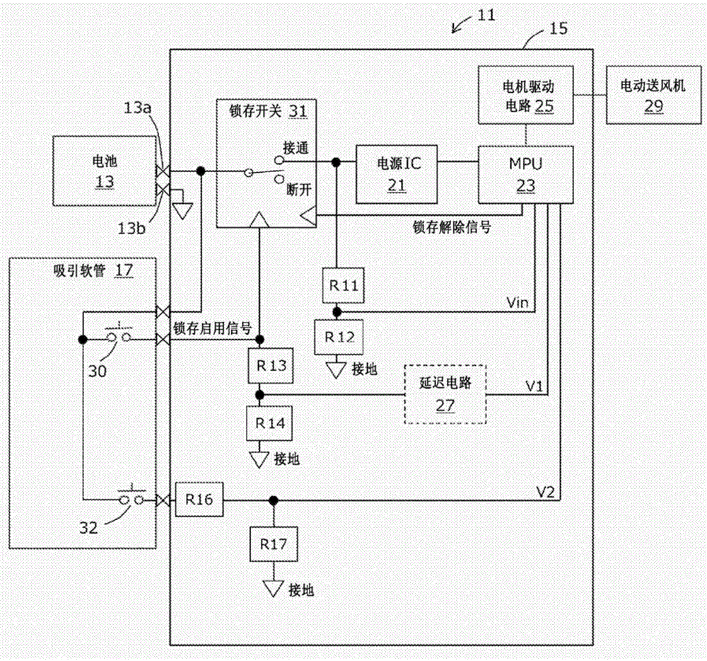
[0028] figure 1 It is explanatory drawing which shows the structural example of the battery-driven vacuum cleaner 11 which is one form of the electronic equipment of this invention. For easy understanding, only the parts deeply related to the present invention are shown, and some well-known elements are omitted. In this embodiment, the cleaner 11 is a canister cleaner, and is roughly divided into a cleaner main body, a suction hose 17 and a battery 13 . The battery 13 and the suction hose 17 are detachable from the vacuum cleaner main body, and are electrically connected via a connector. In addition, the battery 13 has battery terminals 13a and 13b, and is connected to the vacuum cleaner main body via the battery terminals 13a and 13b. The battery 13 is assumed to be a secondary battery such as a lithium ion battery, but is not limited thereto. In the state attached to the vacuum cleaner main body, it may be housed inside the vacuum cleaner main body and covered with a cov...
Embodiment approach 2
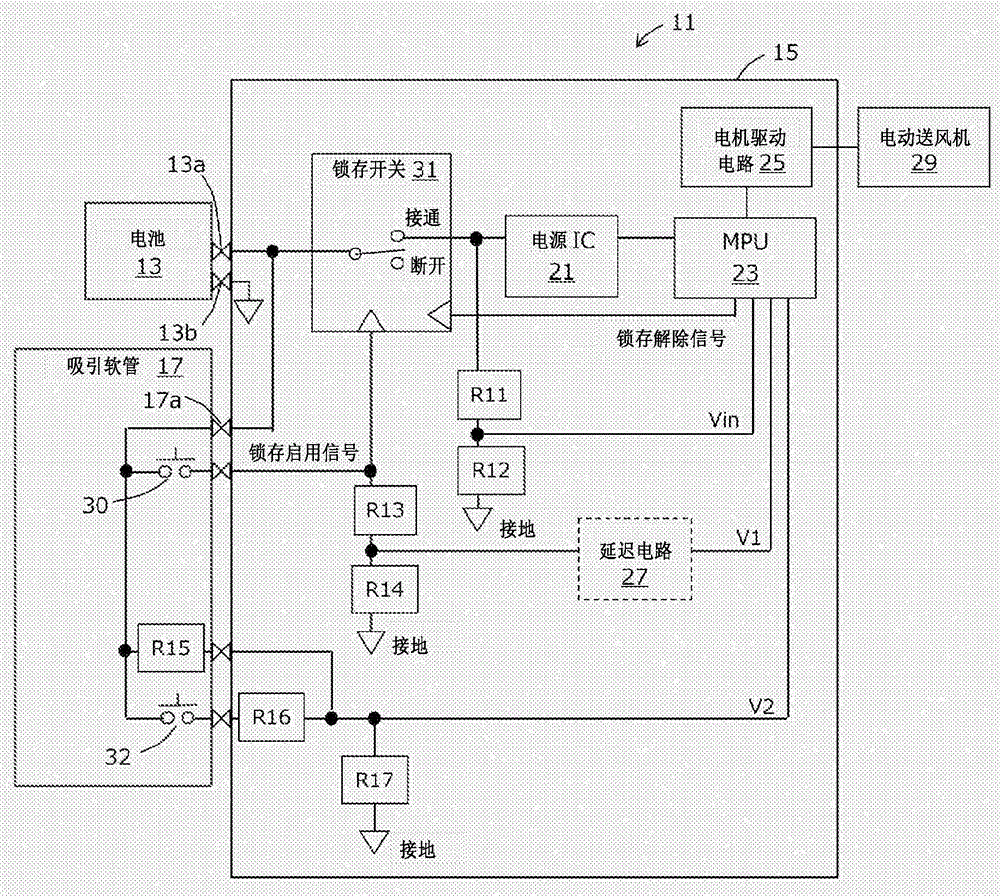
[0048] figure 2 is the same as figure 1 An explanatory diagram of different configuration examples of the vacuum cleaner. right with figure 1 Corresponding parts are marked with the same reference numerals. Description and figure 1 the difference.
[0049] figure 2 Added in is the resistance R15 of the suction hose 17.
[0050] Resistors R15, R16, R17 and cutoff switch 32 correspond to the second voltage dividing circuit of the present invention. The resistor R15 corresponds to a first pull-up resistor, the resistor R16 corresponds to a second pull-up resistor, the resistor R17 corresponds to a ground resistor, and the cutoff switch 32 corresponds to a second momentary switch.
[0051] One end of the resistor R15 and one end of the cutoff switch 32 are both connected to the battery terminal 13a via the connector 17a connecting the suction hose 17 and the cleaner main body. The voltage signal V2 at the connection point of the resistors R16 and R17 is input to the M...
Embodiment approach 3
[0081] as figure 1 As a modified example of the configuration, a method may be considered in which a voltage stabilization circuit similar to that of the power supply IC 21 is used instead of the voltage dividing circuit of the resistors R13 and R14, and the output voltage thereof is read by the MPU 23 as V1. However, since the circuit configuration is more complicated than that of the voltage dividing circuit, it is considered that this leads to an increase in cost.
PUM
 Abstract
Description
Claims
Application Information
 - R&D
- Intellectual Property
- Life Sciences
- Materials
- Tech Scout
- Unparalleled Data Quality
- Higher Quality Content
- 60% Fewer Hallucinations
Browse by: Latest US Patents, China's latest patents, Technical Efficacy Thesaurus, Application Domain, Technology Topic, Popular Technical Reports.
© 2025 PatSnap. All rights reserved.Legal|Privacy policy|Modern Slavery Act Transparency Statement|Sitemap|About US| Contact US: help@patsnap.com


