Supercharge Your Innovation With Domain-Expert AI Agents!

battery-operated electronics

A technology of battery-driven, electronic equipment, applied in the direction of battery disconnect circuit, battery circuit device, electric vehicle, etc.

Active Publication Date: 2018-07-13
SHARP KK
View PDF4 Cites 0 Cited by
  • Summary
  • Abstract
  • Description
  • Claims
  • Application Information

AI Technical Summary

Problems solved by technology

[0004] However, it is not preferable to continue to supply power to the computer during the period when the electronic equipment is not operated from the viewpoint of reducing the consumption of standby power.

Method used


Image

  • battery-operated electronics
  • battery-operated electronics
  • battery-operated electronics

Examples


Embodiment approach 1

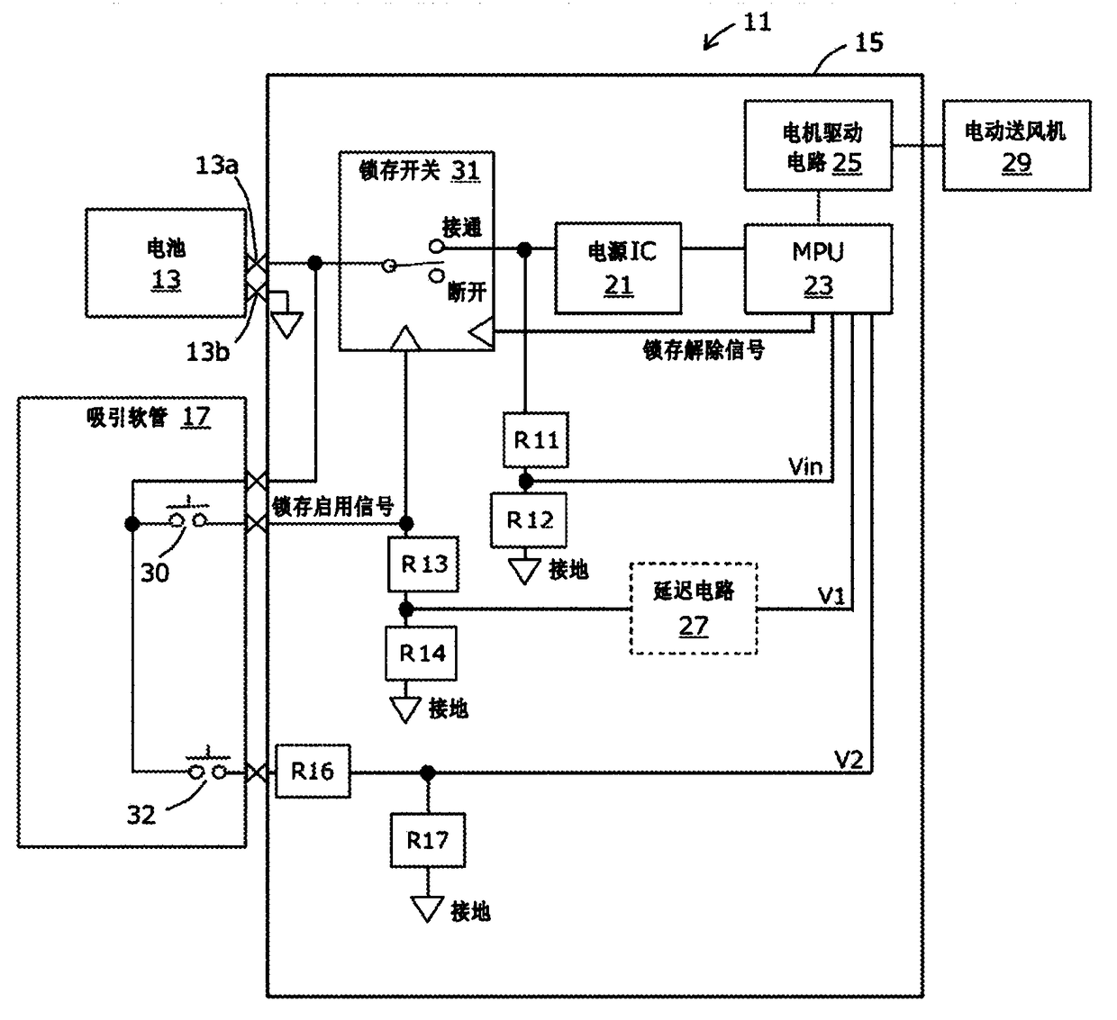
[0028] figure 1 It is an explanatory diagram showing a configuration example of a battery-operated vacuum cleaner 11 which is one mode of the electronic device of the present invention. For ease of understanding, only the parts deeply related to the present invention are shown, and some well-known elements are omitted. In this embodiment, the cleaner 11 is a canister cleaner, and is roughly divided into a cleaner main body, a suction hose 17, and a battery 13. The battery 13 and the suction hose 17 are detachable from the vacuum cleaner main body, and are electrically connected via a connector. Further, the battery 13 has battery terminals 13a and 13b, and is connected to the cleaner main body via the battery terminals 13a and 13b. The battery 13 is assumed to be a secondary battery such as a lithium ion battery, but is not limited thereto. In the state attached to the vacuum cleaner main body, it may be housed inside the vacuum cleaner main body and covered with a cover, ...

Embodiment approach 2

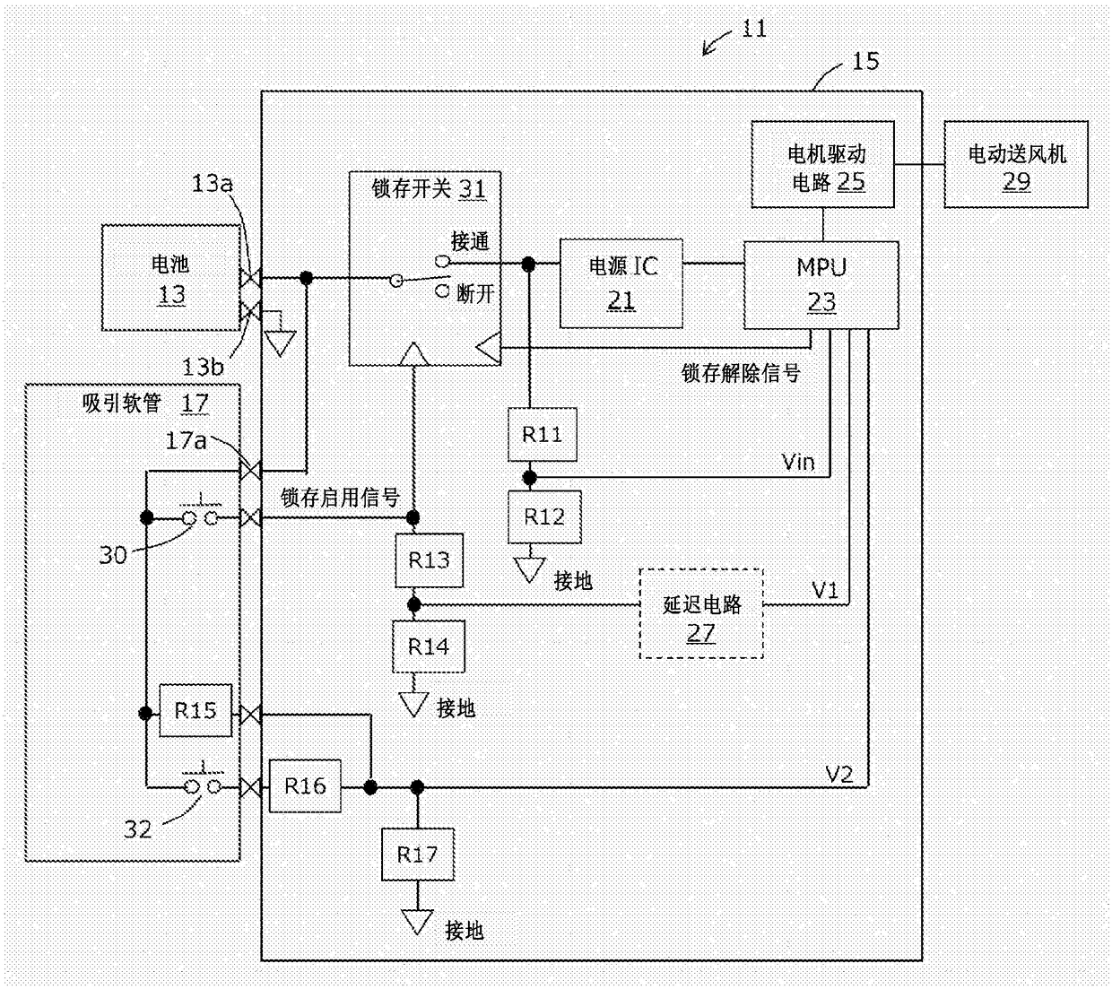
[0048] figure 2 is the same as figure 1 An explanatory diagram of different configuration examples of the vacuum cleaner. right with figure 1 Corresponding parts are marked with the same reference numerals. Description and figure 1 the difference.

[0049] figure 2 Added in is the resistance R15 of the suction hose 17.

[0050] Resistors R15, R16, R17 and cutoff switch 32 correspond to the second voltage dividing circuit of the present invention. The resistor R15 corresponds to a first pull-up resistor, the resistor R16 corresponds to a second pull-up resistor, the resistor R17 corresponds to a ground resistor, and the cutoff switch 32 corresponds to a second momentary switch.

[0051] One end of the resistor R15 and one end of the cut-off switch 32 are both connected to the battery terminal 13a via the connector 17a connecting the suction hose 17 and the main body of the cleaner. The voltage signal V2 at the connection point of the resistors R16 and R17 is input ...

Embodiment approach 3

[0081] as figure 1 As a modified example of the configuration, a method may be considered in which a voltage stabilizing circuit similar to that of the power supply IC 21 is used instead of the voltage dividing circuit of the resistors R13 and R14, and the output voltage thereof is read by the MPU 23 as V1. However, since the circuit configuration is more complicated than that of a voltage dividing circuit, it is considered that this will lead to an increase in cost.


PUM


Abstract

A battery-driven electronic device comprising: a battery having a battery terminal; a computer receiving power supply from the battery; a self-holding type latch switch connected between the battery and the computer to supply power to the computer power supply on and off; a momentary switch which, by turning on, directs the voltage of said battery terminal to the trigger input of said latch switch, which latches said latch switch into an on state; battery monitoring circuit, which converting the voltage of the battery terminal into the computer-readable battery monitor voltage; a switch monitor circuit converting the voltage of the battery terminal via the momentary switch into the computer-readable switch monitor voltage; and a latch release circuit , which turns off the latch switch in response to an output from the computer, the computer compares the switch monitor voltage with the battery monitor voltage when the computer receives power supply and starts processing, and when the difference in voltage exceeds the contact with the momentary switch The above-mentioned latch release circuit is operated in a predetermined range corresponding to the ON state.

Description

technical field [0001] The present invention relates to a battery-driven electronic device, and more specifically, to an electronic device including a computer that operates by receiving power supplied from a battery, and a latch switch that turns the power supply on and off. Background technique [0002] Various electronic devices using batteries as a power source and equipped with computers such as microcomputers are known. In recent years, due to the development of batteries, small, lightweight and high-capacity batteries have become available at low cost. Along with this, not only information processing equipment such as mobile phones with relatively low power consumption, but also battery-driven equipment such as vacuum cleaners equipped with motors are also increasing. However, despite the difference in size, as long as the capacity of the battery is limited, reducing power consumption has always been an issue. [0003] In a battery-driven electronic device equipped ...

Claims


Application Information

Patent Timeline
Patent Type & Authority Patents(China)
IPC IPC(8): G06F1/26H02J1/00H02J7/00H02P29/00
CPCG06F1/26G06F1/3212H02J7/0031H02J7/0063Y02D10/00H02J7/007182
Inventor 中村一良
Owner SHARP KK
Features
  • R&D
  • Intellectual Property
  • Life Sciences
  • Materials
  • Tech Scout
  • Unparalleled Data Quality
  • Higher Quality Content
  • 60% Fewer Hallucinations
Learn More