Circuit breaker with hybrid switch

A technology of AC circuit breakers and switches, which is applied in the field of circuit breakers with hybrid switches, and can solve problems such as the impossibility of short-circuit switching

Active Publication Date: 2016-04-13
EATON IND NETHERLANDS
View PDF8 Cites 23 Cited by
  • Summary
  • Abstract
  • Description
  • Claims
  • Application Information

AI Technical Summary

Problems solved by technology

This makes short-circuit switching impossible si

Method used


Image

  • Circuit breaker with hybrid switch
  • Circuit breaker with hybrid switch
  • Circuit breaker with hybrid switch

Examples


Embodiment Construction

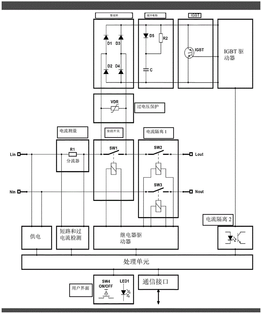
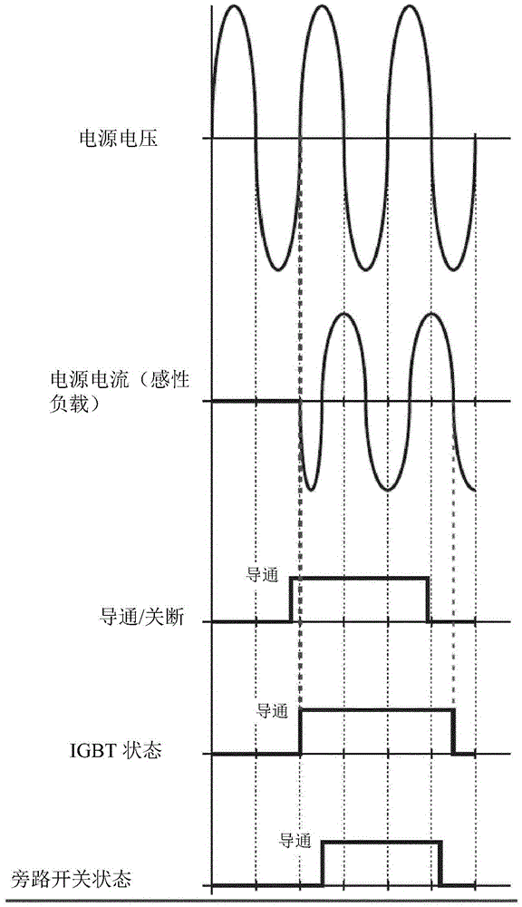
[0036] Reliability and heat dissipation of current short circuit disconnect switches are issues, especially in widely used alternating current (AC) installations. Disconnection of the wires from the load is usually done by a contactor, but any mechanical contactor should be avoided due to reliability and arcing concerns. With current semiconductor technology, it is possible to replace conventional contactors with semiconductors, however semiconductors have a voltage drop. This voltage drop results in a loss of several watts, and this is not permitted or possible in small miniature circuit breaker (MCB) installations. For this reason, parallel (bypass) contactors are used to receive the load current from the semiconductors. However, the switching capacity requirement of a bypass contactor is much lower than that of a conventional (relay) contactor, since the bypass contactor only needs to carry (not switch) current.

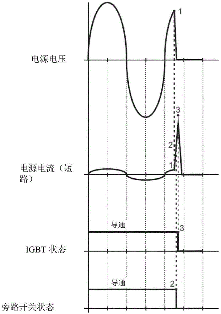
[0037] However, in the event of a short circuit, the b...


PUM


Abstract

Alternating current circuit breaker with a first galvanic separation switch (SW2) and a bypass switch (SW1) in a live line, and a second galvanic separation switch (SW3) in a neutral line, and a semiconductor switch element connected parallel to the bypass switch (SW1). The semiconductor switch element comprises a combination of a rectifier bridge (D1-D4) and an isolated gate bipolar transistor (IGBT). A processing unit is connected to a current measurement unit arranged in the live line, and is arranged to control the bypass switch (SW1), first and second galvanic separation switches (SW2, SW3) and the conducting state of the isolated gate bipolar transistor (IGBT) in case of detection of a short circuit condition.

Description

technical field [0001] The present invention relates to an AC circuit breaker comprising a live wire between a live supply terminal and a live load terminal, and between a neutral supply terminal and a neutral load terminal for connecting an AC load to a mains supply neutral line, comprising a first galvanic isolating switch and a bypass switch on the live line, a second galvanic isolating switch on the neutral line, and semiconductor switching elements connected in parallel to the bypass switch, wherein the processing unit is used to control the first galvanic isolating switch A first and a second galvanic isolation switch, a bypass switch and a semiconductor switching element. Background technique [0002] International Patent Publication No. WO2011 / 018113 discloses a hybrid circuit breaker with a mechanical switch 31 and a semiconductor circuit breaker device 32 connected in parallel with the mechanical switch 31 . An embodiment is disclosed wherein the semiconductor dev...

Claims


Application Information

Patent Timeline
IPC IPC(8): H01H9/54H02H3/10
CPCH01H9/542H01H2009/544H02H3/025H02H3/08H02H7/222H01H2009/543H01H47/223H01H47/32
Inventor R·尼霍夫
Owner EATON IND NETHERLANDS
Why Eureka
Try Eureka