
An ash and fume treatment system for continuous calcination of steel scrap

A processing system and calcination technology, applied in the direction of waste heat treatment, process efficiency improvement, furnace components, etc., can solve the problems of polluted flue gas, unfavorable environmental protection, environmental pollution, etc., to improve the effect, save space, and improve the cleaning efficiency effect of effect

Inactive Publication Date: 2017-09-01
HUNAN XINGUANG FORGING CO LTD
View PDF5 Cites 0 Cited by
  • Summary
  • Abstract
  • Description
  • Claims
  • Application Information

AI Technical Summary

Problems solved by technology

[0003] Most of the existing iron and steel scraps are returned to the furnace for calcination by burning them into molten iron and then pouring them for use. However, there are two forms of existing calcination into molten iron. One is single-furnace calcination. Burning molten iron, and finally pouring out the molten iron, this mode can only be adapted to small-scale production, while the other is to continuously add waste materials to the calciner, and continuously discharge molten iron, and the calcining of iron and steel waste will cause pollution Flue gas contains toxic and harmful sulfides. Therefore, most of them need to be treated with flue gas. There are many ways to treat flue gas. , can achieve very good results, but in order to continuously feed the existing continuous calciner, most of the upper feeding port is open, so a large part of the flue gas will run out from the feeding port and will not enter the processing system The treatment will still cause certain pollution to the environment, which is not conducive to the protection of the environment.

Method used


Image

  • An ash and fume treatment system for continuous calcination of steel scrap
  • An ash and fume treatment system for continuous calcination of steel scrap
  • An ash and fume treatment system for continuous calcination of steel scrap

Examples


Embodiment Construction

[0030] In order to enable those skilled in the art to better understand the technical solution of the present invention, the present invention will be described in detail below in conjunction with the accompanying drawings. The description in this part is only exemplary and explanatory, and should not have any limiting effect on the protection scope of the present invention. .

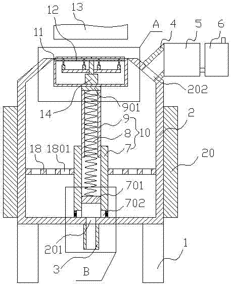
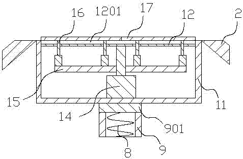
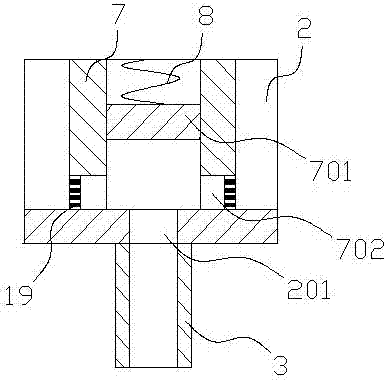
[0031] Such as Figure 1-Figure 3 As shown, the present invention is a gray smoke treatment system for continuous calcination of iron and steel scrap, which includes a support 1 and a calciner 2 arranged thereon. The upper center of the calciner 2 is provided with an annular feeding port, An air outlet 202 is opened on the side of the upper part, a liquid outlet 201 is opened on the bottom, and a temperature control device 20 is arranged on the outside. A turntable 12 is arranged above, and the telescopic rod 10 is installed on the bottom inner surface of the calciner 2, the turntable 12 is flush with...


PUM


Abstract

The invention relates to an ash smoke treatment system for continuous waste steel calcining. The system comprises a support and a calcining furnace arranged on the support, the center of the upper portion of the calcining furnace is provided with an annular charging port, the side face of the upper portion of the calcining furnace is provided with an air outlet, the bottom of the calcining furnace is provided with a liquid outlet, and the outer side of the calcining furnace is provided with a temperature control device; the charging port is matched with an upper cover, a telescopic rod is connected under the upper cover, a rotary table is arranged over the upper cover, the telescopic rod is installed on the inner surface of the bottom of the calcining furnace, the rotary table is flush with the top of the calcining furnace, and an electromagnetic charging device is arranged over the rotary table in a matched mode; the air outlet is connected with a smoke treatment device, and the liquid outlet is connected with a liquid outlet pipe. According to the ash smoke treatment system for continuous waste steel calcining, not only can continuous charging be achieved, but also smoke can be prevented from escaping from the charging port, therefore, the smoke can completely enter a spray device and a sulfide treatment device to achieve good smoke treatment, poisonous gas containing sulfides is prevented from entering air, and then the environmental requirements of secondary waste steel calcining are met.

Description

technical field [0001] The invention relates to the field of calcination environmental protection, in particular to a gray smoke treatment system for continuous calcination of steel waste materials. Background technique [0002] In order to achieve the goal of sustainable development, most of the existing iron and steel scrap materials will be recycled for secondary use, and in the field of iron and steel waste utilization, re-calcination occupies a relatively large proportion. [0003] Most of the existing iron and steel scraps are returned to the furnace for calcination by burning them into molten iron and then pouring them for use. However, there are two forms of existing calcination into molten iron. One is single-furnace calcination. Burning molten iron, and finally pouring out the molten iron, this mode can only be adapted to small-scale production, while the other is to continuously add waste materials to the calciner, and continuously discharge molten iron, and the c...

Claims


Application Information

Patent Timeline
Patent Type & Authority Patents(China)
IPC IPC(8): B01D53/78B01D53/48C21B11/00F27D17/00
CPCB01D53/48B01D53/78C21B11/00F27D17/00Y02P10/20
Inventor 周运五
Owner HUNAN XINGUANG FORGING CO LTD
Learn More