A device for automatically aligning, correcting and positioning a camshaft

A camshaft and automatic technology, applied in the control of workpiece feed movement, grinding machine parts, grinding machines, etc., can solve the problems of high clamping skills of operators, unstable parts processing quality, positioning keyway positioning errors, etc. , to achieve the effects of wide application range, simplified installation requirements, and high angular positioning accuracy

Active Publication Date: 2017-09-05
JACK MACHINE TOOL
View PDF7 Cites 0 Cited by
  • Summary
  • Abstract
  • Description
  • Claims
  • Application Information

AI Technical Summary

Problems solved by technology

Since the positioning parts of the above positioning methods adopt clearance fit, positioning or clamping errors will inevitably result in the processing process, and the positioning error will continue to increase with the wear of the positioning parts. In addition, the positioning keyway and pin hole It will also cause positioning errors due to the burrs not being cleaned up, resulting in unstable processing quality of the parts, and at the same time, the requirements for the clamping skills of the operators are relatively high

Method used


Image

  • A device for automatically aligning, correcting and positioning a camshaft
  • A device for automatically aligning, correcting and positioning a camshaft
  • A device for automatically aligning, correcting and positioning a camshaft

Examples


Embodiment Construction

[0017] The specific embodiment of the present invention is as figure 1 , figure 2 shown.

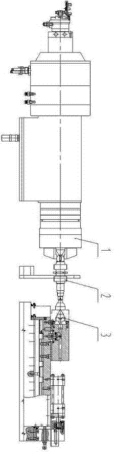
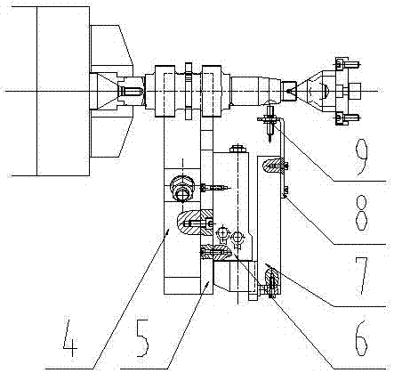
[0018] The camshaft grinding machine of this embodiment is composed of a floating hydraulic chuck 1 on the headstock of the machine tool, an automatic alignment and deviation correction positioning device, a workpiece 2, and a tailstock 3 of the machine tool. The automatic alignment and deviation correction positioning device is installed between the headstock and tailstock of the machine tool. The angle coarse positioning hydraulic cylinder 6 and the angle fine positioning hydraulic cylinder 10 are installed on the connecting plate 5 .

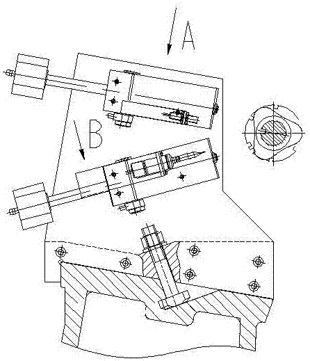
[0019] Angle coarse positioning mechanism such as image 3 As shown, the rough angle positioning mechanism is composed of a rough angle positioning hydraulic cylinder 6, a rough positioning fixed block 7, a rough positioning sensor mounting support 8, and a rough positioning non-contact position sensor 9. The coarse positioning fixed block 7 is ins...


PUM


Abstract

An automatic camshaft aligning, deviation-rectifying and positioning device comprises a coarse angle positioning device and a fine angle positioning device, wherein the coarse angle positioning device and the fine angle positioning device are mounted on an angle positioner mounting seat through a connecting plate, and the angle positioner mounting seat is mounted between a headstock and a tailstock of a machine tool. An automatic camshaft aligning, deviation-rectifying and positioning method for the automatic camshaft aligning, deviation-rectifying and positioning device includes mounting a float hydraulic chuck (1) on the headstock of the machine tool of a cam grinder, mounting the angle positioner mounting seat provided with the automatic camshaft aligning, deviation-rectifying and positioning device (2) between the headstock and the tailstock (3) of the machine tool, driving the coarse angle positioning device and the fine angle positioning device of the automatic camshaft aligning, deviation-rectifying and positioning device by two hydraulic cylinders respectively, providing position signals by a coarse positioning non-contact position sensor of the coarse angle positioning device and a precision positioning sensor of the fine angle positioning device, and combining the float hydraulic chuck on the headstock of the machine tool and a machine tool electric system to achieve automatic camshaft aligning, deviation-rectifying and positioning.

Description

technical field [0001] The invention relates to a device for automatically aligning, correcting and positioning a camshaft, which belongs to the technical field of grinding machines. Background technique [0002] At present, there are several mechanical positioning methods such as keyway type, cylindrical pin type, and conical pin type, which are used in the angular positioning methods of the grinding machine for processing camshaft cams. Since the positioning parts of the above positioning methods adopt clearance fit, positioning or clamping errors will inevitably result in the processing process, and the positioning error will continue to increase with the wear of the positioning parts. In addition, the positioning keyway and pin hole It will also cause positioning errors due to the burrs not being cleaned up, resulting in unstable processing quality of the parts, and at the same time, the requirements for the clamping skills of the operators are relatively high. Content...

Claims


Application Information

Patent Timeline
Patent Type & Authority Patents(China)
IPC IPC(8): B24B49/00B24B19/12
CPCB24B19/12B24B49/00
Inventor 胡建华王玉琢彭灵辉陈志华刘文根刘升愿邹世文稂与飞唐峰
Owner JACK MACHINE TOOL
Why Eureka
Try Eureka