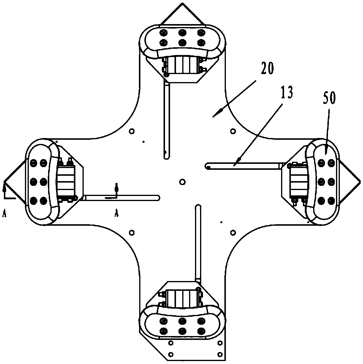
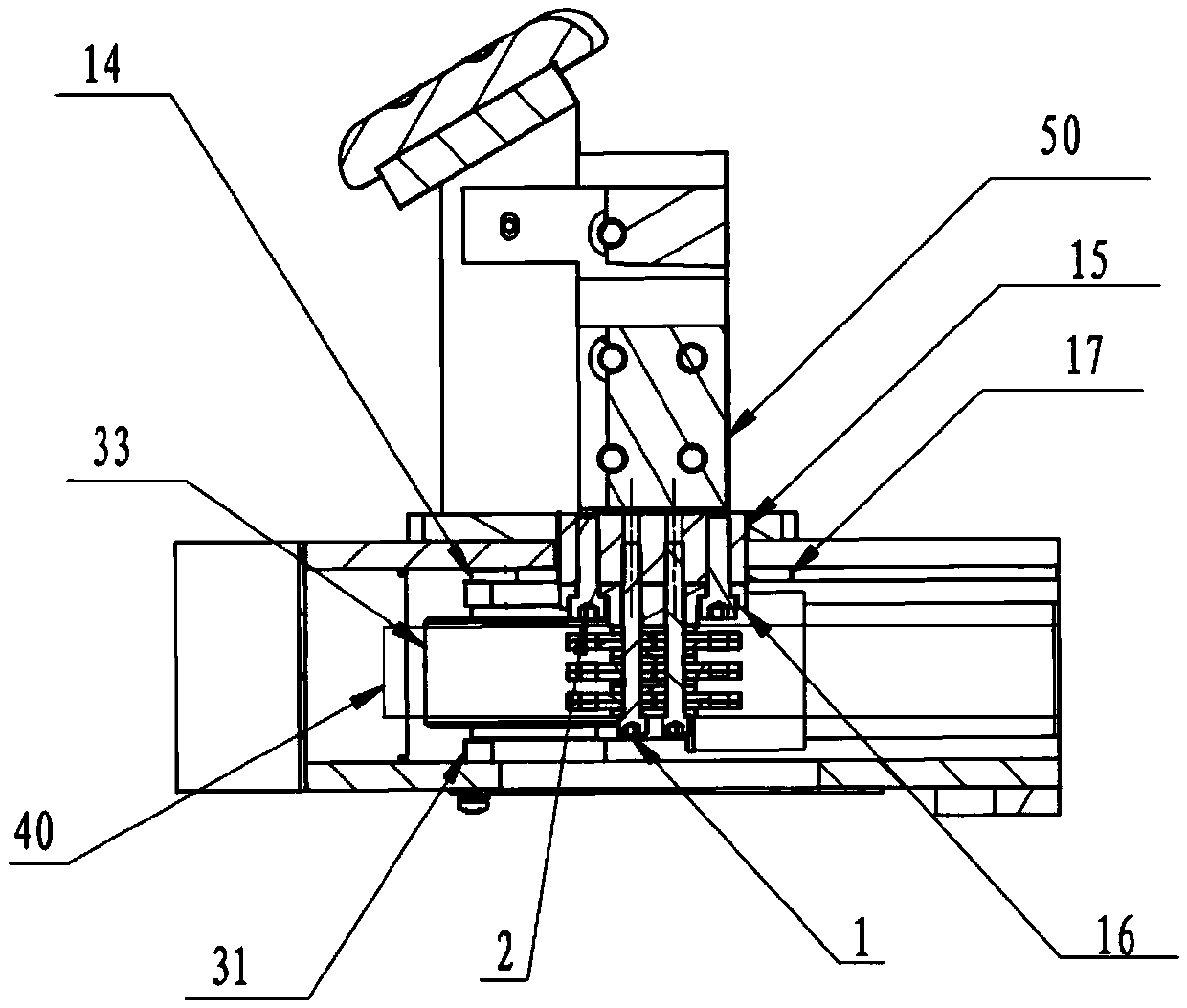
Clamping linkage mechanism and claw disc

A linkage mechanism and clamping technology, used in workpiece clamping devices, manufacturing tools, etc., can solve the problems of time-consuming, labor-intensive, high cost, low work efficiency and other problems of clamping jaws, and achieve simple and ingenious structure, high work efficiency and low cost. Effect

Inactive Publication Date: 2016-04-20
VATAPLE MACHINERY KUNSHAN
View PDF11 Cites 5 Cited by
  • Summary
  • Abstract
  • Description
  • Claims
  • Application Information

AI Technical Summary

Problems solved by technology

However, the cost of the claw plate mechanism equipped with multiple powers is relatively high, and the volume is relatively large
Moreover, during operation, it is time-consuming and labor-intensive to adjust the clamping jaws individually,

Method used


Image

  • Clamping linkage mechanism and claw disc
  • Clamping linkage mechanism and claw disc
  • Clamping linkage mechanism and claw disc

Examples


Embodiment Construction

[0031] In order to realize the synchronous adjustment of the clamping jaws of the claw plate, the traditional solution is that each clamping jaw is equipped with a power mechanism, which can be adjusted one by one or simultaneously to meet the clamping requirements. However, the claw plate mechanism equipped with multiple powers is expensive and bulky. Moreover, during operation, a single adjustment of the clamping jaw takes time and effort, and the work efficiency is low, and due to the existence of errors, even if multiple power mechanisms are adjusted at the same time, the accuracy of the clamping jaw position cannot be guaranteed, and the accuracy is not high.

[0032] In view of the shortcomings in the prior art, the present invention provides a clamping linkage mechanism and a claw plate, so that the whole mechanism only needs a single power to drive a single clamping claw, and the linkage mechanism inside the claw plate realizes the multiple clamping claws. Synchronous adj...


PUM


Abstract

The invention discloses a clamping linkage mechanism and a claw disc. Through cooperation of sheave groups and transmission pieces, clamping claws are fixedly arranged on the transmission pieces, one clamping claw is correspondingly arranged at one side of each sheave group, and the clamping claws are distributed in central symmetry with the center of a bottom plate as the center, and move along with the transmission pieces to move towards the center or away from the center synchronously so as to adjust the size of circumference along which the clamping claws are located. In the whole mechanism, only single power is needed to drive each single clamping claw, and the synchronous adjustment of the plurality of clamping claws is realized through the linkage mechanism in the claw disc. The structure is simple and ingenious, the cost is low, and the work efficiency is high.

Description

Technical field [0001] The invention belongs to the technical field of clamping mechanism design, and specifically relates to a clamping linkage mechanism and a claw plate. Background technique [0002] Because the tires are subjected to the greatest force during take-off and landing, the tires wear quickly, and it is necessary to frequently replace the tire skin and perform flaw detection on the wheel hub for a dozen to dozens of take-off and landing. Due to the heavy weight of airplane tires, one tire weighs more than 100 kilograms, a special equipment tire disassembler is required when replacing tires. [0003] The tire disassembler is a special equipment specially used to separate the tire and the wheel hub. The claw plate is the core component of the tire disassembler. The clamping claws on the claw plate directly clamp the sidewall of the tire. Due to the working needs of the disassembler, the center of the tire It must be located on the axis of the claw plate, and the surro...

Claims


Application Information

Patent Timeline
IPC IPC(8): B25B11/00
CPCB25B11/00
Inventor 赵德清曹猛王峰
Owner VATAPLE MACHINERY KUNSHAN
Why Eureka
Try Eureka