Injection molding machine used for producing plastic products

An injection molding machine and plastic technology, applied in the field of plastic product production equipment, can solve the problems of plastic quality reduction, high metal heat transfer capacity, damage to the nozzle surface, etc., and achieve the effect of consistent deformation and smooth and orderly reciprocating motion

Active Publication Date: 2016-04-20
重庆力标汽车部件有限公司
View PDF4 Cites 4 Cited by
  • Summary
  • Abstract
  • Description
  • Claims
  • Application Information

AI Technical Summary

Problems solved by technology

The problem existing in the existing injection molding machine is that after long-term use, the injection process of the injection molding machine will generate injection pressure between the front plate and the rear plate, which will cause deformation and offset of the injection part, destroy the sliding track of the moving plate, increase the The risk factor of the contact between the barrel and the internal screw is eliminated, and when the nozzle leads out the molten plastic, because the material of the nozzle is generally a metal with strong thermal conductivity, but the large-particle plastic may damage the surface of the nozzle due to the excessive speed during the export process, shortening the The service life of the injection molding machine, and the high heat transfer capacity of the metal will cause sudden condensation and solidification at the nozzle when entering the mold, reducing the quality of the plastic

Method used


Image

  • Injection molding machine used for producing plastic products
  • Injection molding machine used for producing plastic products

Examples


Embodiment Construction

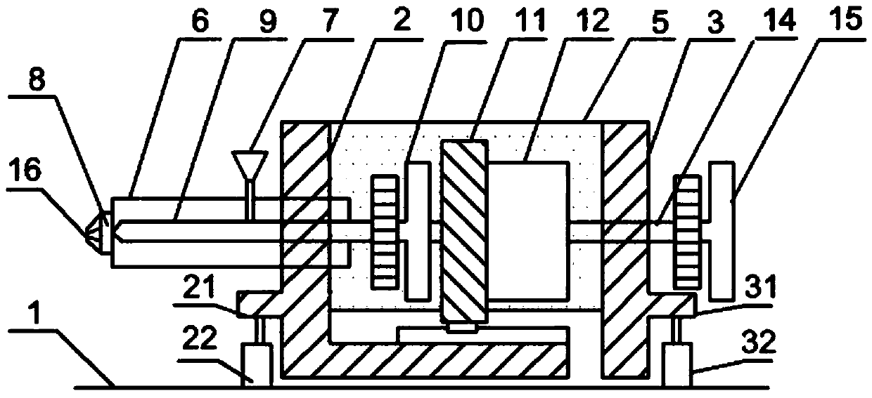
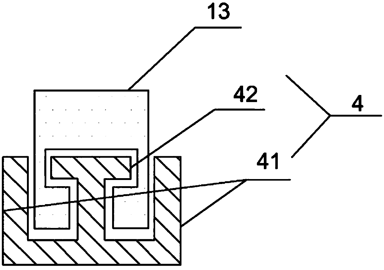
[0029] The present invention will be further described in detail below with reference to the accompanying drawings, so that those skilled in the art can implement it with reference to the description.

[0030] It should be understood that terms such as "having", "comprising" and "including" as used herein do not assign the presence or addition of one or more other elements or combinations thereof.

[0031] In the description of the present invention, the terms "horizontal", "longitudinal", "upper", "lower", "front", "rear", "left", "right", "vertical", "horizontal", " The orientation or positional relationship indicated by "top", "bottom", "inside", "outside", etc. is based on the orientation or positional relationship shown in the accompanying drawings, and is only for the convenience of describing the present invention and simplifying the description, and is not indicated or implied. The device or element referred to must have a particular orientation, be constructed and ope...


PUM


Abstract

The invention discloses an injection molding machine used for producing plastic products, comprising an injection part and a die assembly part, wherein the injection part comprises a base, L-shaped front panel and rear panel, a pair of connecting boards, a charging barrel, a moving board and a second screw; a hopper is arranged at the upper part of the charging barrel, one end of the charging barrel is provided with a nozzle, the other end is sealed, and a first screw is coaxially arranged in the charging barrel; the moving board is provided with a pressure sensor and a nut; a circular-truncated-cone-shaped gum guide body with a sliding block axis of a tenon structure is arranged on the lower surface of the moving board; the bottom surface with relatively small diameter of the gum guide body faces a die; a plurality of notches are formed in the side face of the gum guide body, so as to form a plurality of passages for molten plastics to flow; and the nozzle is of a cylindrical structure, and one end, far away from the hopper, of the nozzle, is detachably provided with a circular-truncated-cone-shaped gum guide body which is coaxial with the nozzle. By adopting the injection molding machine, dislocation and offset caused by injection force or die replacement during injection of a front plate and a rear plate can be avoided, the charging barrel cannot contact with the screws, discharge speed is high, and the nozzle cannot be damaged.

Description

technical field [0001] The invention relates to a production equipment for plastic products. More specifically, the present invention relates to an injection molding machine for producing plastic articles. Background technique [0002] An injection molding machine is a device used to produce plastic products. Typically, an injection molding machine forms a product from polyester, vinyl acetate, different kinds of plastics, nylon, etc. in the form of a melted sheet or powder and places it into a mold with a predetermined shape. The injection molding machine includes a clamping part and an injection part. When the molten plastic is discharged, the nozzle is in contact with the mold to maintain a state in which a predetermined nozzle contact force is applied to the mold. The problem with the existing injection molding machine is that after long-term use, the injection process of the injection molding machine will generate injection pressure between the front plate and the rea...

Claims


Application Information

Patent Timeline
Patent Type & Authority Applications(China)
IPC IPC(8): B29C45/03B29C45/56B29C45/20
CPCB29C45/03B29C45/20B29C45/56B29C2045/202
Inventor 谢飞平何为华刘雪芬
Owner 重庆力标汽车部件有限公司
Why Eureka
Try Eureka